WE 300B single-ended end amp discussion WE300B 245
I have read a lot about the history of WE300B and single-ended on the web page, and I would like to share my experience.
A excellent sounding WE300B single-ended gear has to be good in the following :
1. Power supply
2. Filament
3. drive stage
4. Bias
5. Output transformer
6. tube Selection
7. Miscellaneous: namely chassis, wiring, RCA connector, Grounding wire arrangement, etc.
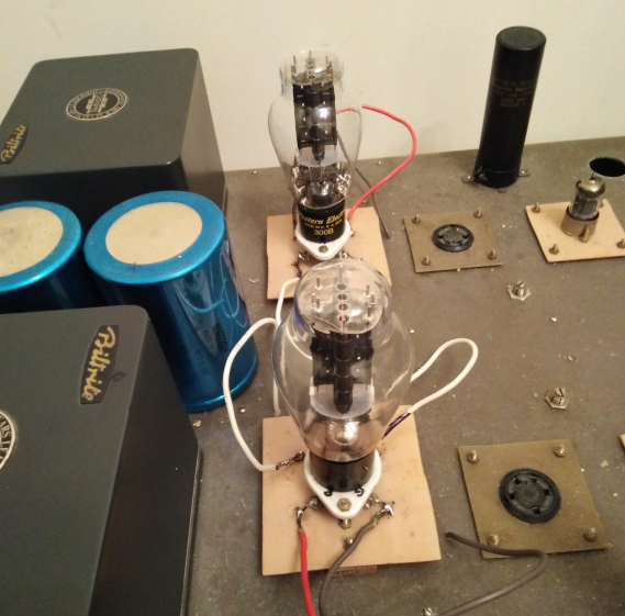
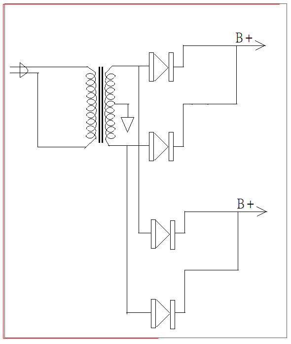
Let me talk about the power supply first. The most ideal is of course a two-channel independent power supply. The problem is that it is not easy to find two power transformers with the same sound. Take a step back using one transformer with dual rectifiers for 300B plate supply, but two sets of rectifier tube filament windings are required. See the picture:

As for the voltage amplifier stage B+, it is better to handle it separately. Don’t share it with 300B. You can use a rectifier tube or semiconductor bridge rectifier:
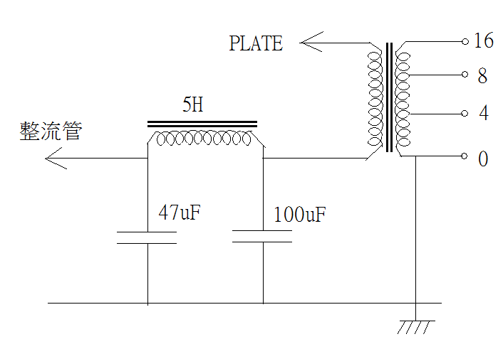
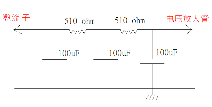
Although the 300B plate B+ and the voltage amplifier stage B+ are processed separately, the high-voltage winding can be shared. Moreover, the negative rectifier from of the high-voltage winding can be used as a 300B fixed negative bias after stepping down, which can do two things with one stone. In terms of filtering, the 300B plate B+ filter Shape CLC sounds more lively, LCLC sounds more pure. Choke does not need to be too large 5H ok, filter capacitor (Blackgate is good), output transformer 10K impedance uses 47uF, 5K uses 100uF, 2.5K uses 200uF (load/ Power impedance ratio), if two-level voltage amplification is used, it is better to share the same B+ than de-coupling (referring to the same channel). 100uF for voltage amplification B+ ok, and there are many other details on the Internet :
As for the B+ voltage of the 300B , the fixed bias circuit can be 320V or 380V, and the self-bias circuit can be 380V or 440V. Higher B+ sounds stronger lower B+ sounds soft, both ok but depends. Each 300B screen current is 60mA, the drive tubes is about 15mA, and the two channels are 150mA in total. The rated current value of the B+ winding must be at least 300mA DC to maintain sound quality.
.
.
The filament looks very simple, nothing more than AC or DC, but it is considered as the most interesting topic.
Actual listening experience has proved that if you don’t mind a small amount of hum, the sound of the AC filament is vivid and attractive. The in-depth analysis of how the AC filament affects the sound is very interesting:
1. Bias hum
The peak value of the AC 5V of the 300B filament is +/-7V. When +7V appears at the filament, assuming that the filament emits uniform electrons and the Trim pot is adjusted to the center position, the center neutral potential of the filament is 0V, and the A terminal to grounded potential is +3.5V and the potential of terminal B to ground is -3.5V, see the picture:
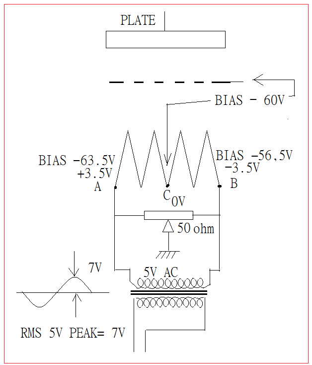
Assuming that the grid BIAS = -60V, then the actual BIAS of A is -60-(+3.5)=-63.5V; and the actual BIAS of B is -60-(-3.5)=-56.5V, it is obvious that the BC segment The filament emits more electrons, while the AC segment filament emits less electrons. Assuming that the filament emits uniform electrons, the increase in the BC segment is exactly the same as the decrease in the AC segment. The total electron flow does not change, that is, the plate current does not change, that is, there is no hum. -7V peak value and vice versa. But if the filament electron emission is uneven and large/ thin edges appear, fine-tuning the Trim pot will move the C point 0V position back and forth along the filament to find a balance and uniformity, which can reduce the biased hum At the lowest level, this is the principle that Trim pot can lower BIAS hum.
The bias hum is the same as the mains frequency (50/60Hz).
2. Temperature hum
Everyone knows that 5V DC and 5V AC RMS have the same resistive load power. See the picture:
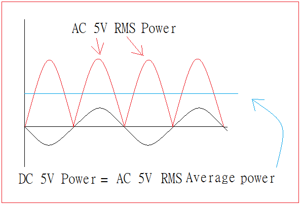
RMS AC power is positive regardless of the positive or negative half-wave power (for pure resistive loads), and the average power is the same as the corresponding DC voltage power, but the instantenous power gose between zero to maximum at twice the mains frequency (100 /120Hz), so the AC filament power is constantly changing.
Because the filament has a heat capacity, when the AC power is zero, the filament temperature will not drop to room temperature, but the temperature will generally be moving up and down around the DC filament temperature, the electron emission also changes with the filament temperature, the high temperature emits more, and the low temperature emits less, which affects the plate current flow and causes hum, see the picture:

The temperature hum is twice the mains frequency (100/120Hz) and cannot be removed, and it is easy to be confused with the B+ rectified residual ripple hum (also 100/120Hz).
.
.
3. Modulation hum
This question is more complicated and abstract, but it is not too difficult to understand after some careful thought.
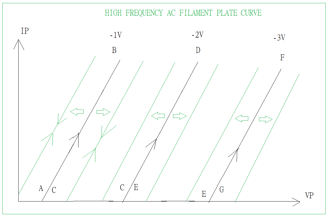
A tube testing power supply consists of pulsating voltage (mains AC full-wave rectification without filtering), negative BIAS Step (step wave) and filament power supply:
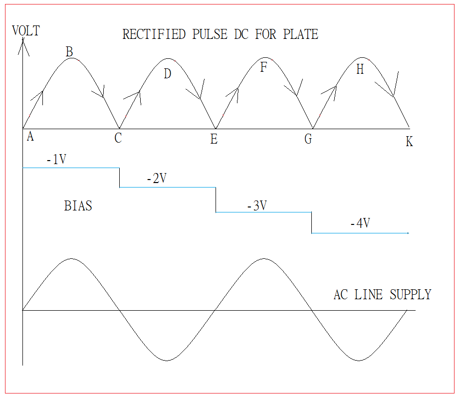
The pulsating DC is connected to the plate, and the -BIAS step is connected to the grid. Assuming that the DC filament as the filament temperature fixed, the screen characteristic curve is as follows:
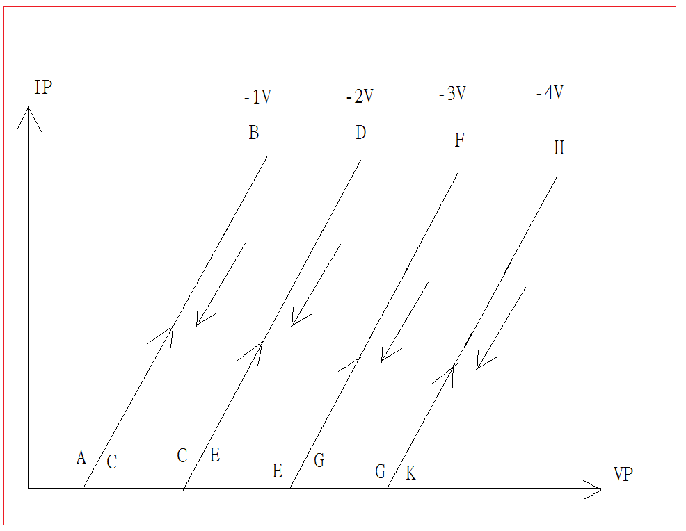
Please note that the curve rises from A to B, and then from B to C. The two lines are theoretically coincident ( in fact there are some slight deviations, but it will not affect the analysis results ) In addition, CD to DE; EF to FG; GH to HK are all coincident, which is not difficult to understand.
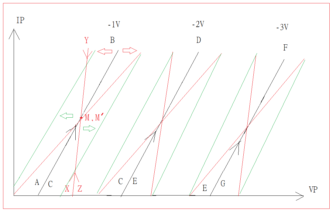
Now let us look at the situation of the AC filament, in the figure M and M’ are the intersection temperature of the AC filament temperature and the DC filament temperature:

The red line in the figure below is the plate characteristic of the AC filament, and the black line is the plate characteristic of the DC filament:
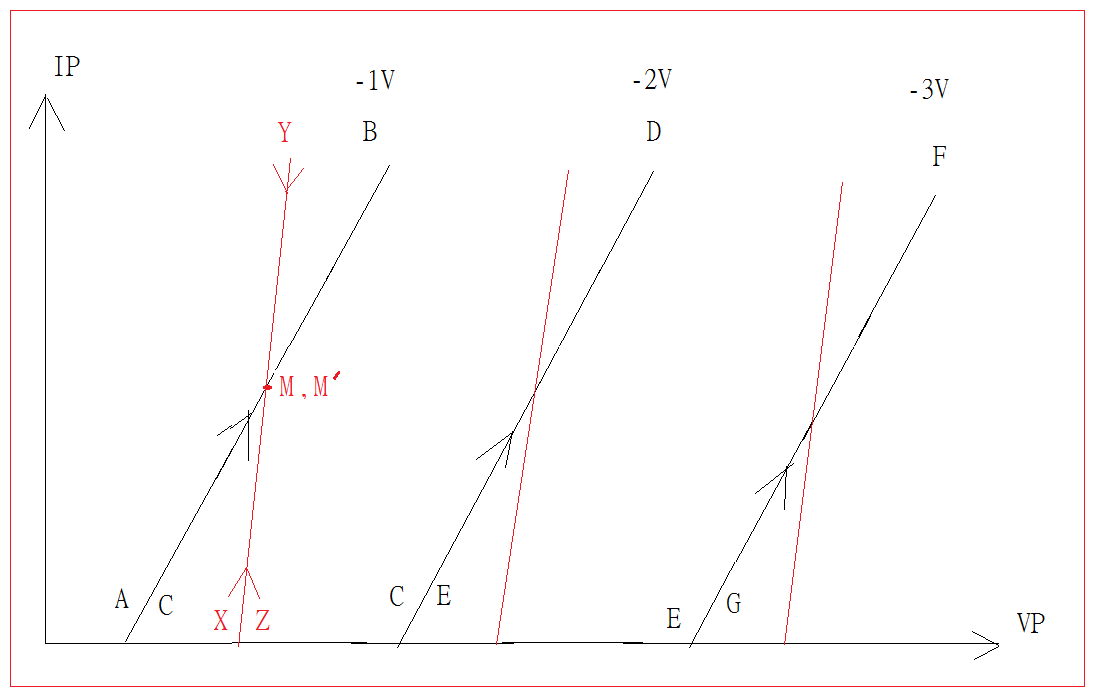
Since the temperature of the AC filament of point X is lower than that of the DC filament, the plate current of point X is lower than that of point A from DC filament.
But the temperature of the AC filament of point Y is higher than that of the DC filament, the plate current of point Y is high than that of point B from DC filament.
The plate current of AC and DC filaments is the same in point M’ and point M’. Theoretically, the XY and YZ lines are also coincident, just like the DC filament AB and BC coincide. The above figure explains that the AC filament changes the plate characteristics (the plate resistance becomes lower).
But the real situation is more complicated, the above figures assume that the filament power phase is the same as the plate voltage phase. There is an often chance that the filament power phase and the plate voltage phase are different by 90 degrees. see the picture:
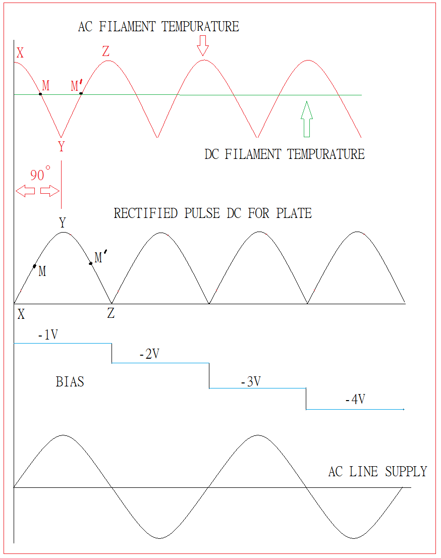
The following figure shows a phase difference of 90 degrees. The red line is the characteristic of the AC filament plate current, and the black line is the characteristic of the DC filament plate current. Since the temperature of the AC filament of X is higher than the temperature of the DC filament, the current of X is higher than the current of A. Also, because the temperature of the AC filament of Y is lower than that of the DC filament, the plate current of Y is lower than that of the DC filament of B. The plate current of the AC and DC filaments in M and M’is the same, the XY and YZ lines are also coincident (in this example, the plate resistance becomes higher). Look at the picture:

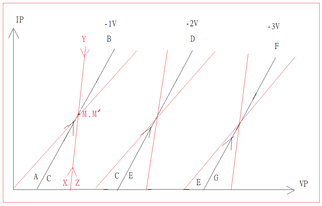
The filament power phase same as the plate voltage phase, and the difference of 90 degrees, two cases are added together (plate resistance keeps getting higher or lower) as shown below:
The filament power frequency is twice that of the mains (100/120Hz), which is a very low frequency. For high frequency signal, for example, 6000Hz is 50 times 120Hz, that is, in the moment that 6000Hz completes one cyele (1/6000=0.1666 mS milliseconds), The filament temperature can be regarded as constant. When the filament temperature is at the highest, the plate current is higher, and the AC filament plate characteristic curve appears on the left of the DC filament plate characteristic curve. At the lowest filament temperature, the plate current is lower. The plate characteristic curve of the filament appears on the right side of the characteristic curve of the DC filament. Look at the picture:
All curves add up as shown below:
In the figure, the black line is the characteristics of the DC filament, the red line is the low-frequency characteristic of the AC filament, and the green line is the high-frequency characteristic of the AC filament. After removing characteristic curve of the DC filament, what left is the plate characteristic modulated by the AC filament. It is dynamic and constantly changing. Through the modulated characteristics, both high and low frequency music signals are modulated. I believe that this is one reason why the AC filament sound is more lively.
.
.
4. Magnetic field hum
Regardless of the grid, when the AC filament current is zero, the filament does not generate any magnetic force, so there is no focusing effect (defocus), and the electron flow will hit on the plate more evenly. See the picture:

However, when the AC filament current is at peak values, the filament current will produce a magnetic force, and the magnetic lines of force have a focusing effect on the electrons. The electron flow will concentrate on the middle of the two magnetic poles, forming an area of electron flow corresponding to the shape of the filament hitting On the plate, see the picture:
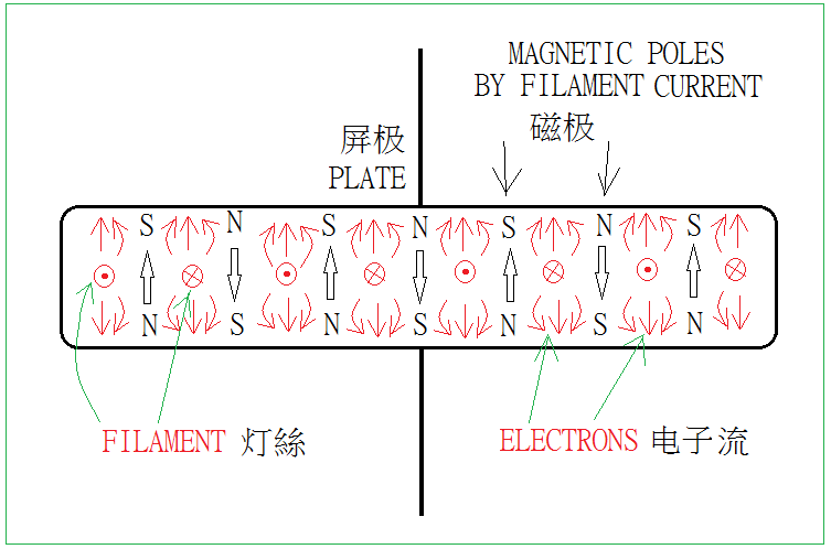
As a result, the electron current hitting the plate will continuously focus and defocus as the AC filament current changes, which affects the sound. I believe that this is also one of the reasons why the AC filament sound is more lively.
Summary of AC and DC filaments:
In actual DIY, if AC filament is used, the rated current value of the transformer filament winding is at least five times the filament current value, otherwise the sound is not atmospheric strong enough, the power consume of the 50 ohm trim pot is 0.5W, use a high quality 5W 50 ohm trim pot.
If a DC filament is used, the rated current value of the transformer filament winding is at least nine times the filament current value, otherwise the sound is not atmospheric strong enough, use a high-quality 25A bridge rectifier, 5000uF high-quality filter capacitor, and it must directly connect to the filament and it is just 5V DC. Bridge rectifier requires four 120pF high-quality capacitors, and 5000uF filter capacitor requires one 0.22uF high-quality capacitor; and 50 ohm trim pot cannot be replaced by two 25 ohm resistors, because it is still residual ripple to trim.
.
.
Driver stage
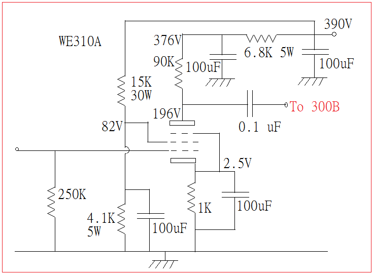
Western Electric 91A amp uses the WE310A pentode connection method to push the 300B. This is famous, but unfortunately I have never heard of it. The tube 310A is also expensive and difficult to be found. However, personally I would not perfer pentode connection. See the following picture (plate current 2mA, 2nd grid current 0.5mA), anyone interested could take a try:
At present, the more popular methods are 6SN7 two-stage direct couple connection (SUN AUDIO), 6SL7/12AX7 SRPP capacitor couple, and there is no need to add a cathode follower to the SRPP , otherwise it is not SRPP. (For details, please refer to the article on SRPP Amplifier Theory)
Those one stage driving with high transconductance (Gm) tube, is not recommended.
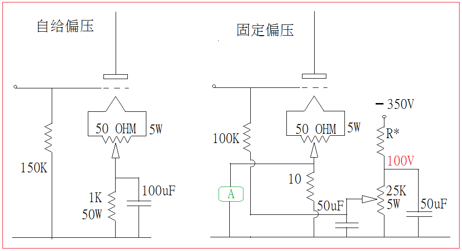
Here is a simple two-stage drive, the overall gain is about 120, B+ can be from 300V to 380V, and the fixed bias of the drive stage is a more special way, but the sound is very good, please see the picture:
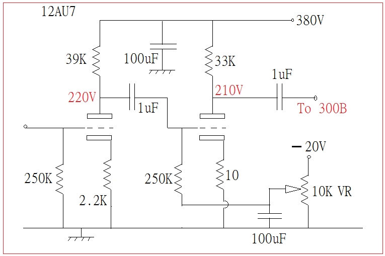
In the self-bias, The 1K cathode resistor and 100uF bypass capacitor have a decisive effect on the sound. High-quality parts are required.
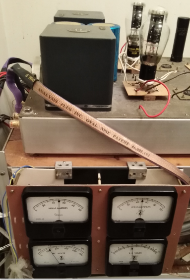
The fixed bias negative volt came from the plate supply winding (-350V). Voltage drop resistor R* is easy to calculate using Ohm’s law, 10 ohm resistor is designed for ammeter, in fact, it is a voltmeter, because the ammeter cannot be directly connected to the circuit will affect the sound quality, regardless of the fixed or self bias, all parts must be high quality.
.
.
The output transformer is the most challenging and important component. Please refer to my article “Discussion and Testing of Single-Ended Output Transformers”, here is a supplement, let’s review the iron core hysteresis loop characteristic curve:
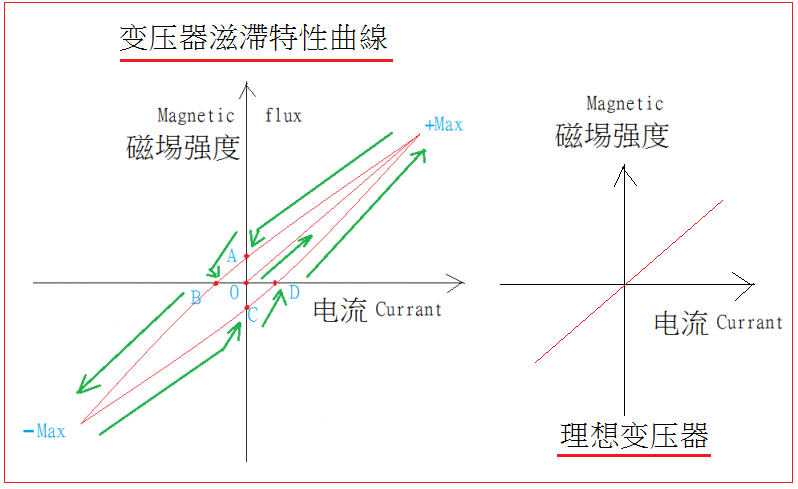
The electric current increases from the O point to the +Max point. The magnetic field strength also increases to the +Max point. Then the current is decreasing and so as the magnetic field strength, then the current at point A has dropped to zero but there is still magnetic strength (remanence). Until the reverse current increases to point B, the remanence is cancelled, and the reverse current increases to -MAX so as the magnetic strength also to the -Max point. Then the current is reducing to 0, but there is still magnetic strength (remanence) until the forward current increases to point D to cancel the remanence magnet field, and then forward current increases. The magnetic strength also increases to +Max, which completes a cycle. If there is no remanence, the magnetic hysteresis characteristic curve will be a straight line, which is the ideal transformer.
Now we can talk about the characteristic curve of the moving loop of the speaker voice coil:

The voice coil current starts from O point and the forward current increases to M, but the voice coil still does not move. It is because the friction of the bounce spider and cone surround are not overcome, the forward current continues to increase, then the voice coil starts to move, and the current increases to + The MAX voice coil shift is also increased to +Max point, then the current is less and the voice coil shift is also less , but the current has dropped to 0 when it reaches point A, but the voice coil still fails to return to the original position of 0, which is also because of the frictional force, until the reverse current increases to point B enough to offsets the frictional force and returns to the original position of 0, then the reverse current increases the voice coil reverse displacement also increases to the point -Max maximum point, and then When the current drop, the voice coil shift is also drop, but the reverse current has dropped to 0 and the voice coil has not returned to the original position until the forward current increases to D point. When the positive current increases, the voice coil shift also increases to the maximum point of +Max to complete a cycle. If there is no friction, the voice coil characteristic curve will be a straight line, that is, an ideal speaker. This is known as speaker hysteresis characteristic.
The friction force affects the sound quality of the speaker, the smaller the frictional force, the more the sound details. High-quality output transformers and speakers have the smallest area hysteresis characteristic curve, of course , The most extreme example is a straight line , but no matter how small the area of the hysteresis characteristic curve is, it will not be a true straight line. If we examin the curve near the point O, you can see the following picture:
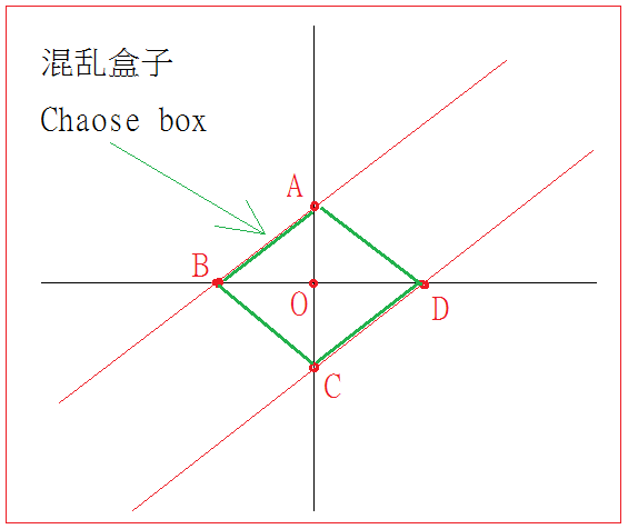
The diamond formed by ABCD in the picture is called the chaose box. The bigger the chaose box, the worse the sound, the smaller the chaose box, the better the sound and the more details. The output transformer and the speaker cannot be directly compared because they are different physical quantities, but the voice coil current of the speaker is supplied by the output transformer. There is a physical connection between the two, so after weighted quantification (mathematical operation), two chaotic boxes It can be directly compared. There are three situations here. One is that the two boxes are the same. There is no problem with matching each other. The second is that the output transformer box is large. Then we need to change a smaller box transformer to improve the sound. Third, the speaker box is large. Then change a speaker with a smaller box to improve the sound, so that after chasing each other, the sound gradually becomes better. Among the equipment I have listened , the speaker has the smallest chaotic box is ALTEX 288 sun edge metal diaphragm, and the JXL 375 is the second good, Tamurx F2013 output transformer has the smallest chaose box.

.
.
The output transformer and 300B’s operating point:
Primary 2.5K 13H 65mA net plate voltage 350V plate power consumption 22.8 W output power 5.3 W
Primary 3.3K 17H 65mA net plate voltage 350V plate power consumption 22.8 W output power 7.1 W
Primary 5.0K 13H 55mA net plate voltage 400V plate power consumption 22.0 W output power 7.5 W
Primary 5.0K 13H 60mA net plate voltage 450V plate power consumption 27.0 W output power 9.0 W
Primary 10 K 50H 36mA net plate voltage 450V plate power consumption 16.2 W output power 6.5 W
The above arrangement is theoretically the same as the low-frequency cut-off frequency calculation result of 32Hz (-3db), but it is true that the sense of hearing is different. It is suggested that the internal resistance of the 300B plate is 800Ω, and three times that of the 2.5K primary impedance is enough for output transformer.
According to the low-frequency cut-off frequency of 32Hz (-3db), it is suggested that enough primary inductance of 13H, and the number of turns is not much, which can effectively reduce the stray capacitance of the primary and secondary coils, and improve the high-frequency response without affecting the low-frequency response. It seems that smart tricks, but there is no free lunch in the world, even regardless of the 13H leading to low frequency and intermediate frequency not thick enough, the 2.5K primary impedance output wattage is the least, because there is no negative feedback, the damping factor that can control the woofer is also the smallest, then the low frequency reproduction is not good, low cost and easy to build is the truth.
5K 25H is preferable because the output is up to 9W and the mid-to-low frequency is thicker, and the damping factor is also good. As for the 10K 50H, of course the mid-to-low frequency is the thickest, and the damping factor is also the largest, which can take care the woofer well, but the winding stray capacity is large, but the frequency response of the beautiful iron core coiled by the famous factory should still reach above 50KHz, which is enough for fun. 8Ω speakers can be connected to 16Ω Tag to play 5K, and 4Ω Tag can be used to play 20K. Low plate current tube uses 10K/20K transformer The wattage is relatively large, even if 10K is equipped with 300B, it has 6.5W and the plate consumes only 16 watts and is durable. The only drawback is that it is large, heavy and expensive. It is crazy to play with a 40W transformer at 0.5W, but everyone knows that playing HiFi is not To be rational. The final choice of 5K 25H or 10K 50H depends on personal decision, the other is not advisable.
Finally, the concept of single-ended power amplifier does not have a negative feedback for best result is widely recognized by DIYers. Without the help of negative feedback, there are only three ways to subdue the large and heavy woofer. One is sufficient and solid low-frequency response. The second is very small low-frequency distortion, and the third is a sufficiently high damping factor. That is, first, the primary inductance and the static plate current are large enough, the second is the beuatiful hysteresis characteristic curve, and the third is the high primary impedance. This is all physical law of the jungle cannot be changed. If this law is violated, the low frequency replay is no good.
Tube selection is simple, the old WE300B is the first choice, the Reissue is the second choice, and then other brands are selected.
As for the voltage-amplified 12AX7/U7 and 6SN7, have to use 1960s American or European brands such as RCA, GE, SYVANIA, TUNGSOL, TELEFUNKEN, etc., which are worth the money. There are also some unpopular American old 2C50 and JAN 7193, RCA 6FQ7 clrar top, etc., I will tell you after the audition.
Finally, there are miscellaneous items. The power and output transformers should not be too small in size, also the chassis should not be too small, at least 16 inches X 12 inches X 2.5 inches, the aluminum sheet must be 2.5 mm thick, and the steel sheet must be 1.5 mm thick, otherwise the sound is not bright enough,
the parts location arrangement, the power supply is at the last end side, and the two channels of output transformers are side by side, and then the power tube, the voltage amplifier tube, the volume control(50K or 100K available) and the RCA input plug are at the front, the noise problem in the power amp is not a big issue. The ground wire is made of a T-shaped with 2.5 mm thick copper wire, and it can go from the beginning to the end of chassis. The T-shaped copper wire is already connected to the chassis at one point, and other parts only be connected to T-shaped wire but not the chassis, this is the original intention of one point grounding to chassis.
In short, to make a 300B power amplifier, use AC filament, cool transformers and good tubes with high quality capacitors, and a large chassis. It is simple, the entry level is not high, everyone can build it without exaggeration.
The same is true for 2A3 245 71A single-ended amps.
Thank you for visiting
.
.