RIAA RC basic RC network principle is simple please see picture:
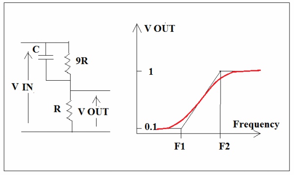
(RIAA RC basic network)
In low frequency C almost open then 9R and R deliver 0.1Vin to output.
In high frequency C almost shorted circuitand deliver 1Vin to output.
F1 and F2 are known as turning frequencies which determined by R and C time constant.
Actually time constant = RC which is a time required to go through one radius angle, a completed cycle is 2π radius.In this case if 9RC=3180 μs, 3180x2x3.1416=19980 μs.
Since 1000000μs/19980μs=50cycles/second=50Hz.
If 9R and R connected in parallel it is equal to 0.9R, then 0.9RC=318 μs that means 500Hz.
If we carefully choose R and C,F1 and F2 will be 50Hz and 500Hz respectively to fit RIAA curve. Again, we make another similar network using 75 μs and 7.5μs then F3 and F4 will be about 2100Hz and 21KHz respectively.Two networks connected in cascode will complete the RIAA curve, see picture:
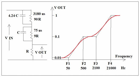
(Inverse RIAA completed network)
In low frequency range, the 75 μs part C as if opened and 9R+R= 10R this is similar to basic network but the output now is from 0.01 Vin to 0.1 Vin due to 9R and R ladder giving 1/10 of standard output level. In high frequency range, the 3180 μs part 4.24C as if shorted circuit , then C , 9R and R form a basic network giving 0.1 Vin to 1Vin output level.
The overall response curve is match the RIAA requirement and this network and curve are known as Inverse RIAA response.
Now we make the network up side down and the curve will be up side down as well, see picture:
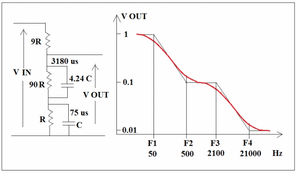
(Forward RIAA completed network)
In low frequency range both C and 4.24C as if opened so that the output is 0.9Vin, in mid range 500Hz the 4.24C as if shorted cct and C remains as if open the output is about 0.1Vin, in high range both C and 4.24C as if shorted the output tended to be zero. This network and curve are known as Forward RIAA response. In general practice, the 90R will be taken off because the
value are too big as few mega ohm, this will also boost up the low frequency end output from 0.9Vin to almost 1Vin. ( for tube amps)
The basic principle of RIAA network is simple and clear, there is a standard RIAA curve developed and most phono amp makers had followed as a common practices, please see picture:
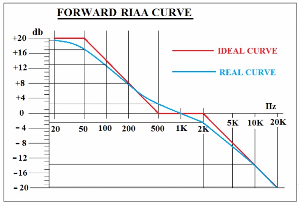
(Standard forward RIAA curve)
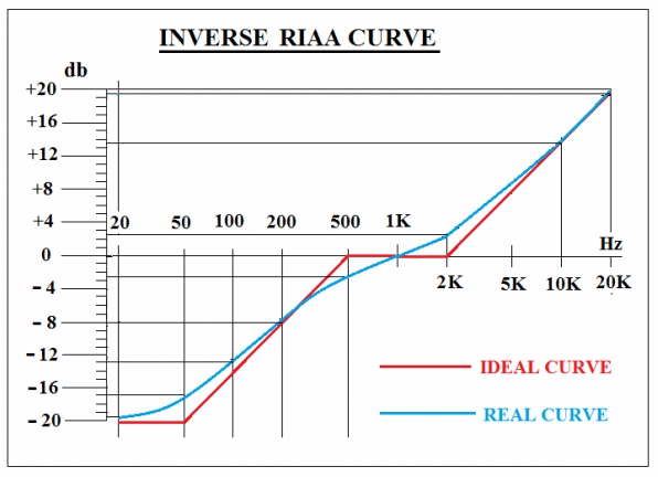
(Standard inverse RIAA curve)
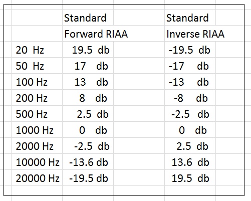
(Standard RIAA key frequencies response)
Phono amp DIYers could roughly estimate the time constant by RC value to see weather matches3180 μsand 75μsor not. From my experience 1.5 or two db drift from standard curve will affect the sound reproduction and human ear can identify the difference.
I use the above example to create a RIAA inverse network and tested by mathematical formula got such a result, see picture:
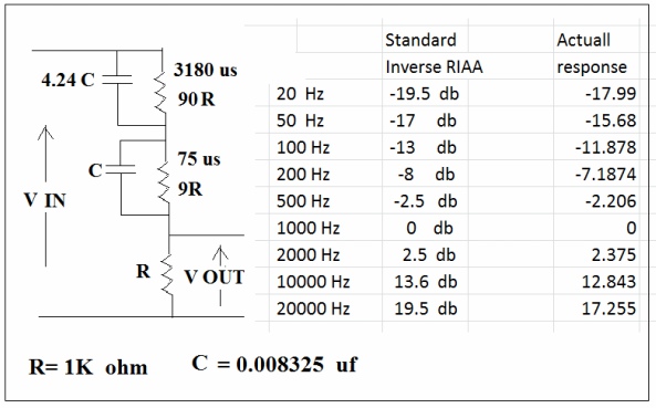
There are two db difference in both low side and high side, by experience I suppose the base is a bit weak and high will be too bright. So that the RC value has to be fine tuned to fit the standard.
There are lots of information in the inter net telling about how to design a RIAA network,I suppose those design calculations are approximations trying to match the RIAA standard as much as possible. But very rare of information telling about how to confirm the network response stick to standard curve. May be some computer program packages from the market can help, users can input the RC values of the network and then the program will calculate and give the result both in graphic and figures. The only thing we can do is to trust it.
Of cause we can measure and fine tune the curve by signal generator and oscilloscope but we have to build the machine first. Actually we don’t have to because we can develop a mathematical formula for the network to find out the detail response in specific key frequencies. The detail mathematical formula derive is boring, anybody interested please refer to my “RIAA network analysis” article.
There are two major type of RIAA phono amps, negative feedback type and forward RC coupled type, the negative feedback type uses inverse RIAA network while the RC coupled type uses forward RIAA network.
The famous M7 phono amp is feedback type inverse RIAA network please see picture:
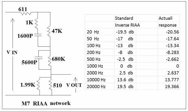
(M7 phono amp inverse RIAA network)
Where 611 ohm is output impedance of the cathode follower, 1.99K is input impedance of the feedback point.47000x.0016= 75.2 μs quite matches, 680000x.0056= 3808 μs which is about 20% more than 3180 μs. But the overall response is very close to that of standard.
Actually I built the machine like this:
The response is ok but the feedback loop involves two voltage amp stage and one cathode follower stage so that it is a bit long, and then the high frequency detail resolution is affected but it will give a worm sound , still a very good design in that ages.
I also tried a RC coupled forward type RIAA amp like this , please see picture:
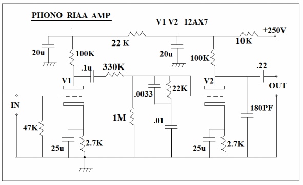
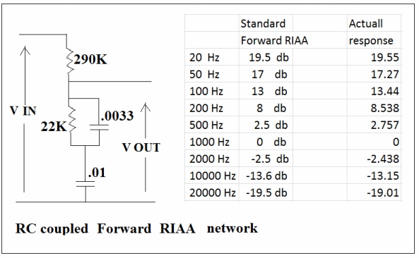
(RC coupled forward type RIAA network response)
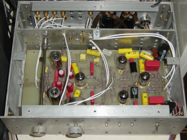
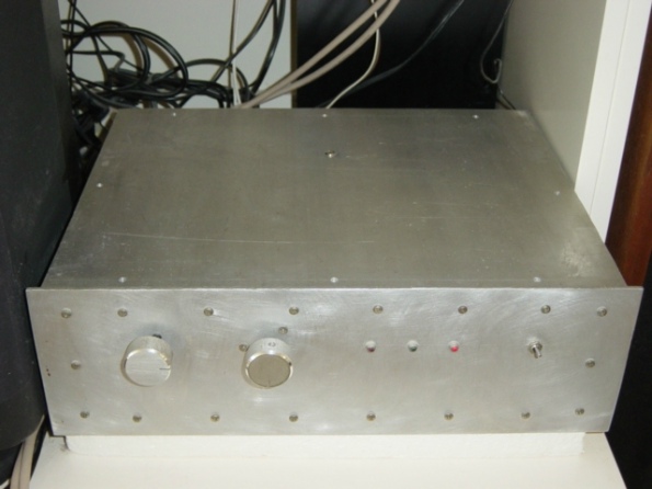
The response is excellent stick to standard, actually I built the machine as a prototype for testing purpose like this:
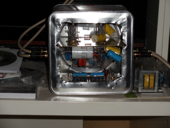
It sounds excellent with brisk high and tight bases, simple is the best, a very good design.
I suppose most RIAA amps are based on above mentioned networks and the results are more or less the same. Somebody suggested LC networks for this purpose and claimed high end results, the problem is very difficult to get high quality chokes with few henry inductance and of cause the very high price.
Thanks for visiting.