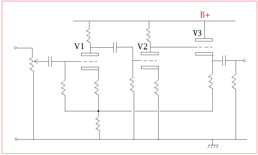
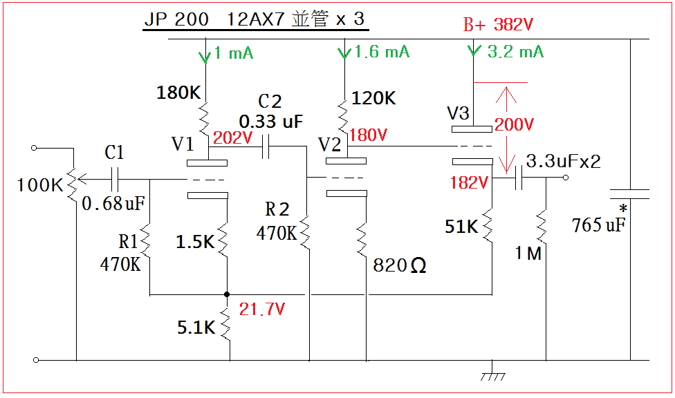
JADIS’s flagship preamp JP200 has European and Asian versions. The European version uses EF86 as triode connection to create a balanced amplifier, so each side uses six EF86s. The Asian version using the popular 12AX7 connected in parallel, the online information shows that JP200 is simply the parallel connected version of JP80, the basic structure is the same, I have seen the JP200 internal photo confirmed that it might use 12AX7, 12AT7 or 6DJ8 by pin welding judgment, resistance and capacitance value is not clear in the photo, The JP 200 is a very good machine. It is worth a try from the DIY point of view. There are many different versions of the online information. There may be no one is genuine but the basic structure is the same, please note that V3 output stage cathode connected to the feedback resistor, so that the cathode to ground resistor is therefore no longer needed, see picture:
The basic concept of Jadis JP200 is derived from the Marantz M7, two common cathode stages with NFB , but had undergone considerable changes.
1. The first stage voltage amplifying cathode bias resistor is separated from the NFB return resistor to make the circuit dynamic and more stable, and greatly improve the low frequency.
2. The overall NFB return loop also includes the cathode follower output stage, which softens the sound. The deep NFB could make the distortion low and expand the bandwidth. The second stage plate directly connected to the grid of the cathode follower and the NFB return is also directly connected without a capacitor, so that the frequency response is very amazing, easily reaching 0.07Hz to 150KHz (0 db), also improve for the low frequency.
3. The triode connected in parallel method enhances the mid-frequency vocal thickness and also improves the high frequency, so this arrangement was obviously working for more sound touching .
Due to the characteristics of 12AX7, for better sound, the common cathode stage plate voltage should not be less then 160V and the cathode follower stage plate voltage should not be less then 180V. Therefore, this machine chooses 180V for common cathode and 200V for cathode follower.
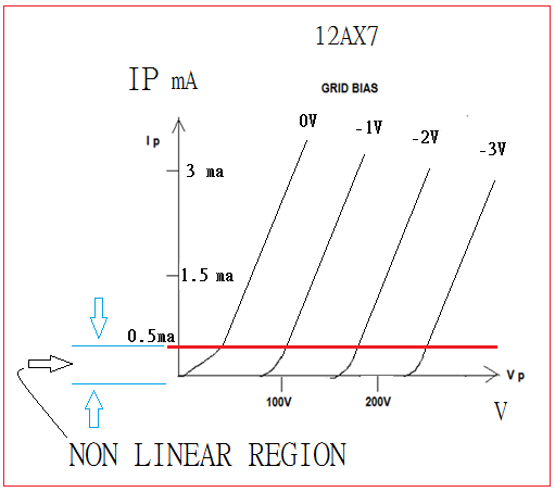
The second stage is directly connected to the cathode follower, so we need a 200+180=380V B+ power supply. There are too many different versions online, the resistance value and the capacitance value are all different so it is hard to follow. We can start from the plate current estimating, in order to avoid the nonlinear region of 12AX7 characteristic graph, the first stage plate current is 0.5 mA, the second stage plate current is 0.8 mA, and the cathode follower is 1.6 mA. For paralleled tubes they are doubled as 1 mA, 1.6 mA and 3.2 mA respectively. After selecting the best working voltage, it is easy to calculate the resistor value. Please see the picture:

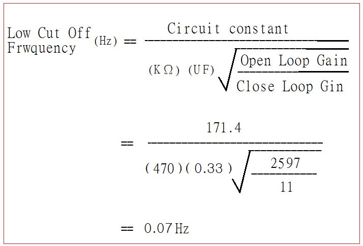
The first stage common cathode gain is 50, the second stage common cathode gain is 53, and the third stage buffer stage cathode follower gain is 0.98, which greatly reduces the output impedance and increases the output force, by adding a deep NFB, the closed loop gain is about 11 and the NFB is 47.5dB.
Open loop gain = (first stage common cathode gain) x (second stage common cathode gain) x (third stage cathode follower gain)
=50 x 53 x 0.98
= 2597
Closed loop gain = 11
JP200’s direct NFB circuit design without a capacitor is really a true tube master, the ultra-low frequency response is extremely amazing, the replay low frequency invincibly reaches 0.07Hz (0db), determined by R2, C2 time constant, open loop gain, closed loop gain and circuit constant:

This 0.07Hz low frequency response does not seem to be a problem, because the tube power amplifier does not reach that frequency response. The problem is in the preamp itself. If there is a 0.07Hz signal input, the amplified signal will appear on the output. The output stage itself is fine. Because B+ is up to hundreds of volts, this ten-volt signal output is nothing, but this 0.07Hz signal changes extremely slowly and creates a continuously heavy loading to power supply , it will affect other frequencies, so the power supply of this machine should withstand the extra requirement of this 0.07Hz very low frequency signal.
The two stage common cathode plus NFB has extremely low and high frequency response with overall good performance. So it is worthwhile to pay for good result , if the design does not use this two level common cathode plus NFB concept, will not get better results.
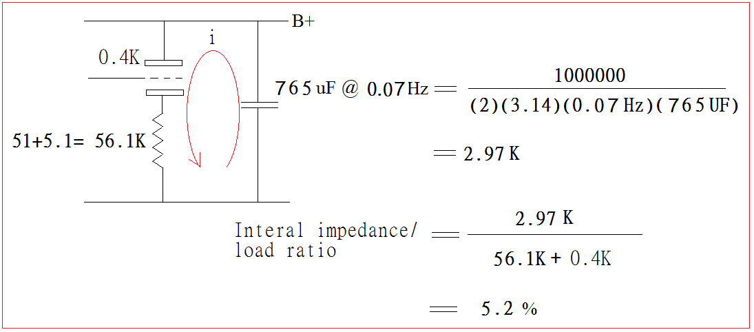
If we do not recognize this very low frequency signal and randomly change the value of the coupling capacitors for better sound, the consequences are unpredictable. To solve the influence of the additional requirement of the 0.07 Hz very low frequency signal on the power supply, have to understand the power supply internal impedance / load impedance ratio, which is simply the power supply internal impedance compare with the load at a specific frequency.
The smaller the ratio the better , and could not be greater than 5%, in order to balance the effect of this very low frequency replay.
Please see the cathode resistance of the final cathode output is 51K+5.1K= 56.1K plus 12AX7 tube cathode output internal resistance 40K/100=0.4K ie 56.5K, this is the load resistance, a 760uF filter capacitor at 0.07Hz AC impedance is 2.97K, within the power supply The impedance load ratio is 2.97 K/56.5K= 5.2%, which is OK. This is why the JP200 filter capacitor uses such a big value. Some one suggested a low-impedance regulated power supply can do also , however, to built a low-impedance regulated power supply is not difficult but it is difficult to get good sound. Using high quality 760uF capacitor is the simplest and straightforward method.
Some friends said that they had experienced large value filter capacitors used in DIY equipment are really low frequency bloated and turbid. This is because the capacitor poles are rolled into a round barrel put in the aluminum cans. The large capacity positive and negative sheets are long and rolled up, so the inductance will be large enough to attenuate the high frequency signal so as the low frequency is swollen.
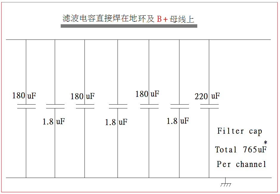
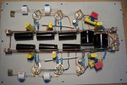
It is necessary to use high quality small capacitors in parallel. For example, five 200uF are connected in parallel and used as 1000uF. The original JP 200 is used in multiples parallel. In addition, the large filter capacitor is also known as the large reservoir, it will cause sound turbidity when it is placed on side and then connected with long wires. It is good to use the shortest distance by soldering directly on the circuit, even it is no good looking enough but still desirable, this is very important, and will be explained in detail when implementing the welding proses.
To install JP200, follow the following three formulas:
R1=R2
C1=2(C2)
Filter Capacitance Value (uF) = (C2)(R2)/0.203
=(0.33)(470)/0.203
= 760 uF
If the value of the filter capacitor is insufficient, the low frequency lacks of good sense, so that the filter capacitor capacity must be sufficient. If the value of C2 R2 is changed, the whole circuit will be affected. (If C2 is changed to 0.47uF, C1 should use 1uF, filter capacitor should be 1000uF, low cutoff frequency is 0.05Hz.) Please note that the three stage circuit using only one B+ and decoupling no needed, trust me, it is too complicate to explain at this moment.
The 765 uF filter capacitor consists of 7 capacitors, 1.8uF is a high-quality plastic film capacitor used to improve the high frequency. It can be used from 0.1 to 2.2 uF. The whole set of capacitors is directly soldered to the circuit to form the shortest distance.
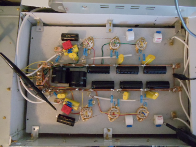
Actual building process:
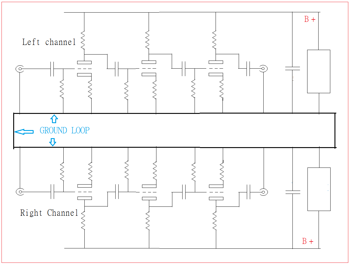
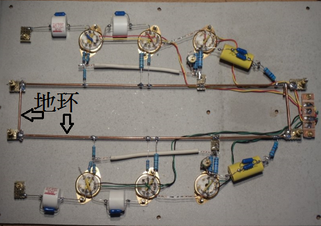
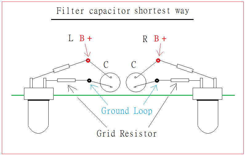
Experience tells us that point to point soldering is the best, it is not easy to achieve the formal performance of JP200. DIY friends have experience with Marantz7 would be less difficult to built JP200. The popular trend emphasizes single point grounding as it can reduce hum and noise. I really don’t know when this was raised, by the legend, without a single point grounding arrangement might be considered as not advance enough. However, my point of view , unnecessary welding point added, unnecessary wiring lengthened, so that the mutual induction between wires are enhanced and the sound quality is affected. Please see the comparison:

Please take a look at this, called the ground loop method, it seems to be unusual, but the loop will induce the alternating magnetic field into a current to cancel the magnetic field itself(according to Lenz’s law), if the loop resistance is low enough, The induced voltage is negligible (below 0.1 uV) and can be neglected. The most important thing is to provide the shortest path of the filter capacitor.
power supply
For the preamplifier, a stable B+ power supply is a must. If not, a good amplifier circuit design will be wasted. The original power supply design is a low frequency signal generator to create a 400Hz sine wave signal, driving by two 2N3773 power transistors, a special step-up transformer, raises the output voltage to 400Hz 400VAC, the voltage after rectification and filtering is up to 500VDC, and then the EF86, EL84, constitutes the closed-loop voltage regulator circuit, and the output stabilized voltage is 380VDC, but the closed loop voltage regulator circuit is not fast enough, the B+ output must be connected in series with a resistor of about 500 ohms to improve the tone. There are three tubes per channel, B+ current is about 6mA, but there is a very large power supply filter capacitor, the capacity is more than 1500uF, because the current supplied by the regulated power supply is very small, it takes a considerable time for the filter capacitor to be charged full, an operational amplifier formed a voltage Comparator, when the voltage of the filter capacitor rises to the reference voltage, the relay will deliver the music signal to output so as ensure the sound quality. The original power supply specification DIY is not easy, yet the closed-loop regulator circuit is slow in front of a 150KHz signal, so the output wants a 500 ohms resistor.
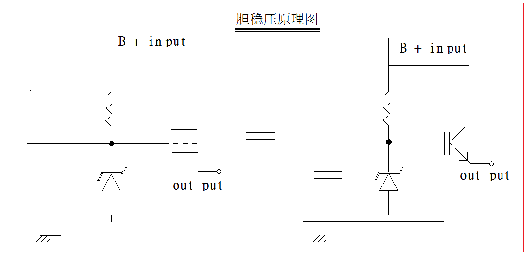
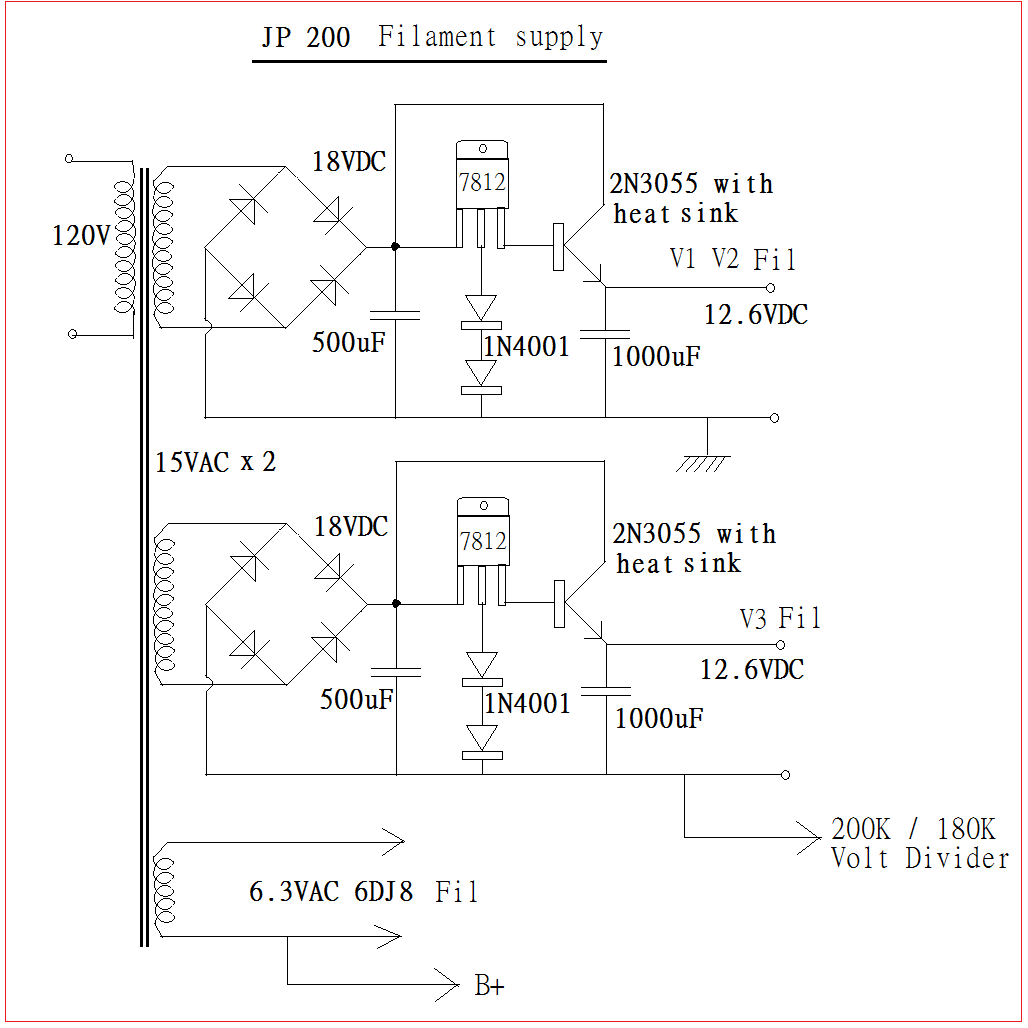
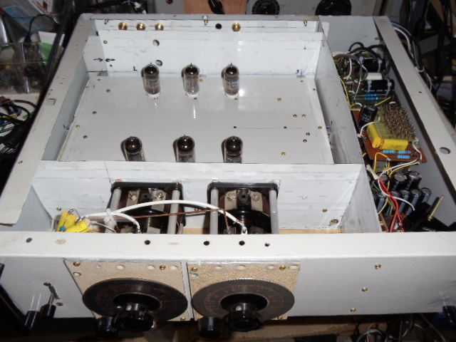
A very simple DIT fast open loop regulator uses 6DJ8, which was originally designed for VHF (Very High Frequency), easy to reach 50MHz, working in audio more than enough, 200mW 7.5V Zener diode 51 piece connect in series get 382V (you can also use twelve 30V Zener diodes), with 6DJ8 has good sound, please see the B+ The power supply does not get any resistor in path to reach the amplifier, this is very important for the sound quality, and even the three stage decoupling resistor in the machine is also removed. Please see the picture:
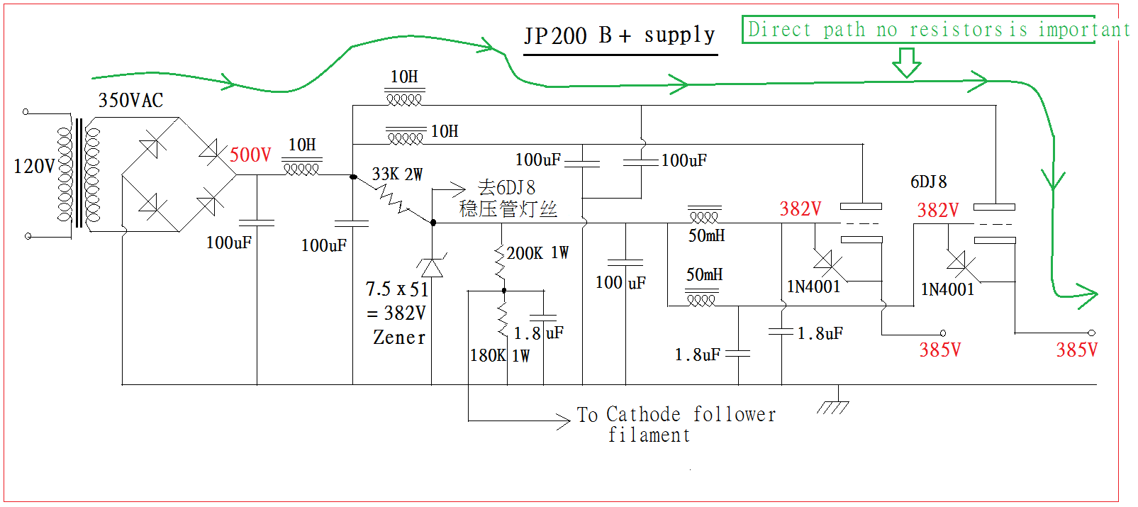
If DIY friends who like tube rectification, there is nothing wrong with it. Just increase the plate winding to 365VAC. The full wave winding is 365VAC x 2 plus the rectifier tube filament power supply 5VAC. It can play different rectifier tube for different sounds, and different factories 6DJ8 sounds different as well, it is a fun.
Stabilized 12.6V DC for filament are necessary otherwise there will be hum, cathode output stage filament Power supply had to connected to a voltage divider close to the cathode potential, see picture:
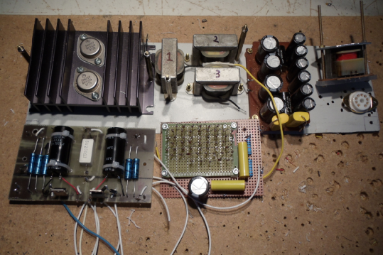
Power supply power supply (partial):
Tube selection:
The most important thing is the selection of the vacuum tube. The 12AX7 small-signal tube is selected. JP200 has a total of 6 tubes, use the 1960s RCA, GE 12AX7 or the European Siemens, Telefunken ECC83 are very good. .
My select Tetefunken Telefunken ECC83
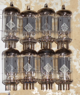
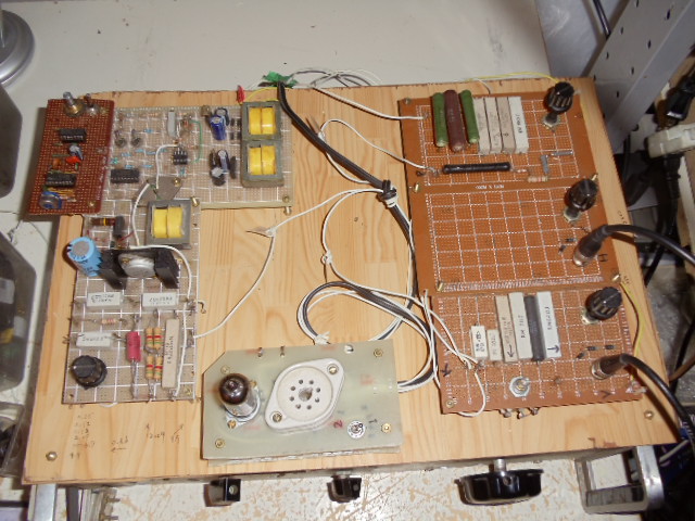
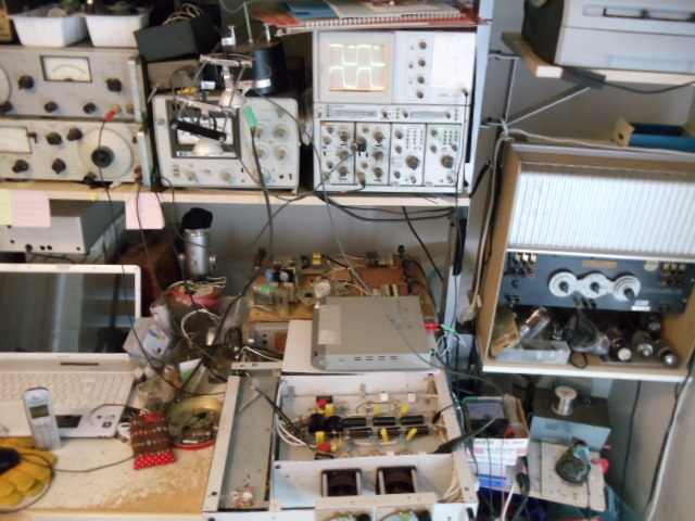
The first stage, the second stage and the third stage of the tube are all equally important , the characteristics of the two triodes in each glass envelope wanted to be close to each other, so a vacuum tube characteristic curve scanner was built , using selector switch to quickly convert the tube, compare it on the oscilloscope screen, and find the same characteristic tube, please see the picture:
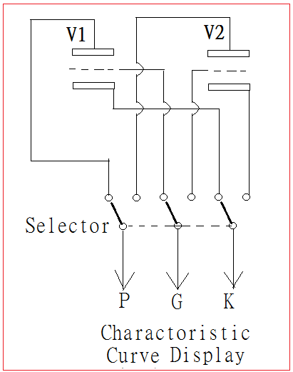
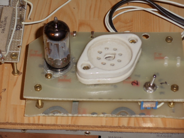
The scanner is composed of classical digital integrated circuits CMOS 4538, 4081, 4040, operational amplifier TL082 and high voltage transistors in the 1970s and 1980s. The characteristic curve is displayed on the oscilloscope screen:
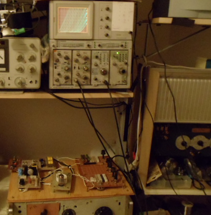
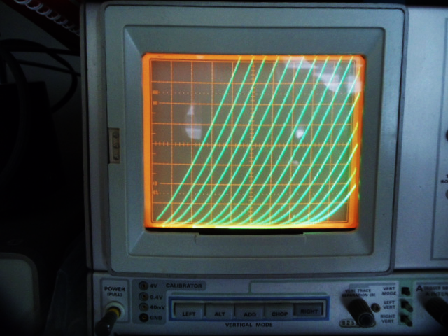
The sixteen characteristic curves completely cover the entire working range of the tube, and the matching is accurate to ensure the sound effect:
The coupling capacitors of different brand name different sound .The WIMA MKP10, Solen, Mundorf EVO and supreme are used below. One more thing, capacitors are not necessarily famous if the loss factor is less than 0.0003, the sound is not bad.
test
To know that the JP200’s NFB network without capacitor design and parallel tube operation, the machine is extremely amazing regardless of the high frequency and low frequency: 0.07Hz to 150KHz (0db)
Unlike the sine wave, the square wave test is a side mirror, no matter the frequency, overshoot, and ringing, all of which show the characteristics of the machine nakedly. Because of the parallel tubes, the square wave response of this machine is up to 100KHz, which is the remarkable achievement of JADIS circuit designers.
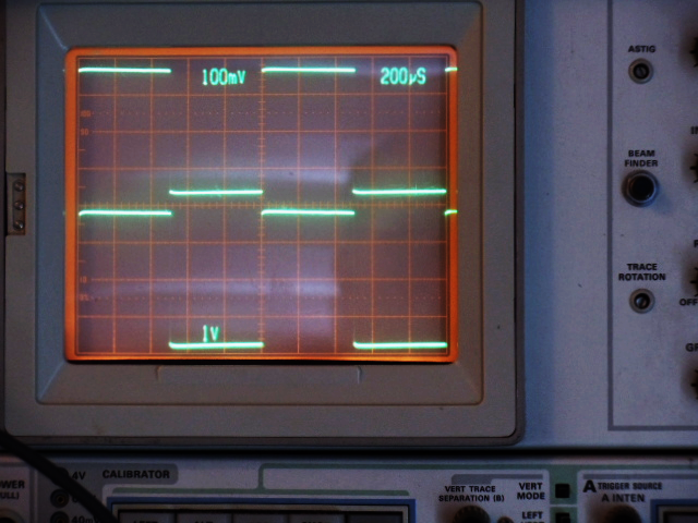
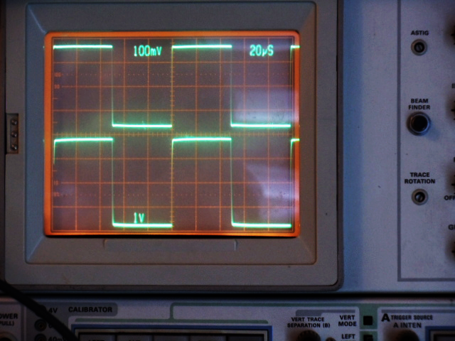
The number on the oscilloscope refers to the value per division, input 100mV per division, output 1V per division
Square wave response 1KHz time base signal 200uS per division
Square wave response 10KHz time base signal 20uS per division
Square wave response 20KHz time base signal 10uS per division

Square wave response 50KHz time base signal 5uS per division

Square wave response 100KHz time base signal 2uS per division

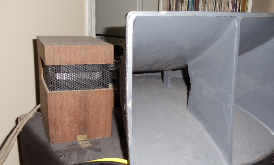
The huge American RSA MET 9 II aluminum ribbon tweeter emits a very high treble, because its sound-emitting aluminum ribbon has a width of 1.3 CM and a total length of 25 CM, which is much longer than the average, so it needs a huge magnet, the engineer invented and manufactured this object considers it is too expensive , so the production is not massive. The treble is really good and has texture and thickness, next to the corner of ALTEC 311_60 To compare the size.
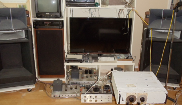
Listening
The JP 200 uses a parallel management method to enhance the vocal thickness and greatly improve the high frequency. After a few hours of downtime, it gradually enters the good mood.
The treble is sweet, the middle is thick, the bass is clean and refreshing, the high, medium and low frequencies are balanced, the distortion is extremely low, the dynamic range is wide, and even at high volume, there is no uncomfortable, and at the same time, the thickness of the human voice can be maintained, and the detail analysis is strong and The sound field is wide and deep.
After the audition, the structure of the machine has been fixed, the resistors, capacitors value should not be changed, there is no objection to upgrading the high-quality capacitor resistor and the wiring inside the machine, and the volume potentiometer also.
Thank you for your visit.