Stereo is a voice reproduction technique to display a sound stage in which many sound images can be identified at different positions as similar to actual life experiences. This wants two speakers work together, one speaker system known as mono can only give music but not sound stages. The foundation of any sound or voice is the sine waves, some what likes the prime numbers of mathematics, sine waves could not be disassembled or divided into two or more components.
Carefully calculated combinations of sine waves can form any sound or voice, say in other words, any sound wave form can be divided into a series of sine waves. (Fourier series). I will try to explain the sine wave in a simplest way as this is a very important basic knowledge for achieving sharp sound images in Hi Fi stereo systems.
A triangle OAB has an angle C , it is defined that Sin(angle C)= AB/ OB (the length ratio of line AB and line OB), please see picture 1 :
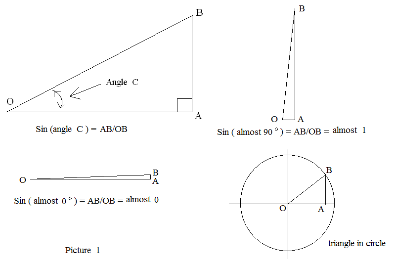
We then put this triangle in to a circle , the point O is the center and the line OB is the radius. Let us examine the sine wave as angle C varies from 0 degree, to 45 degree, 90 degree, 135 degree, 180 degree, 225 degree, 270 degree, 315 degree and 360 degrees( one cycle completed). As the line AB is always vertical, in upper half of the circle line AB is positive (pointing up) while in lower half circle line AB is negative (pointing down), and don’t ask me why, the line OB is ALWAYS positive no matter upper or lower half.
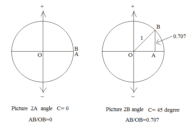
Ok, for angle C = 0 degree line OA and line OB stack together so that line AB= 0 length, so that Sin( 0 degree)= AB/OB= 0. (see picture 2 A ) For angle C = 45 degree Sin (45 degree)= AB/OB = 0.707 (see picture 2 B )
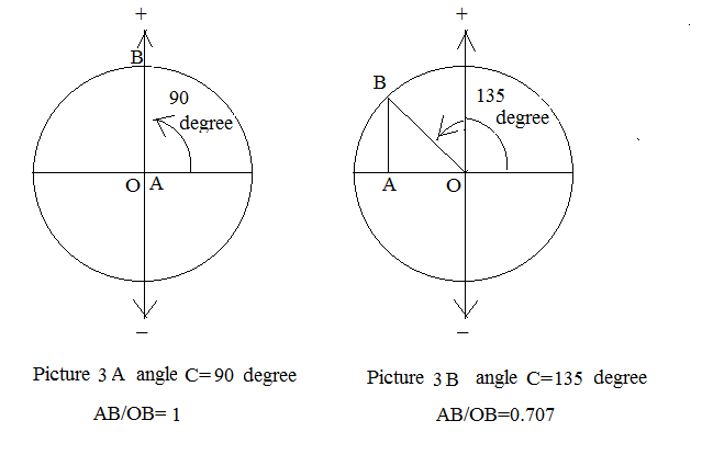
For angle C = 90 degree Sin ( C )= AB/OB= 1 (see picture 3A )
For angle C =135 degree Sin ( C )= AB/OB= 0.707 (see picture 3B )
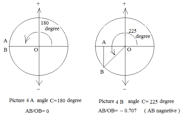
For angle C = 180 degree Sin ( C )= AB/OB= 0 (see picture 4A )
For angle C =225 degree Sin ( C )= AB/OB= – 0.707 (see picture 4B )
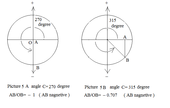
For angle C = 270 degree Sin ( C )= AB/OB= -1 (see picture 5A )
For angle C =315 degree Sin ( C )= AB/OB= – 0.707 (see picture 5B )
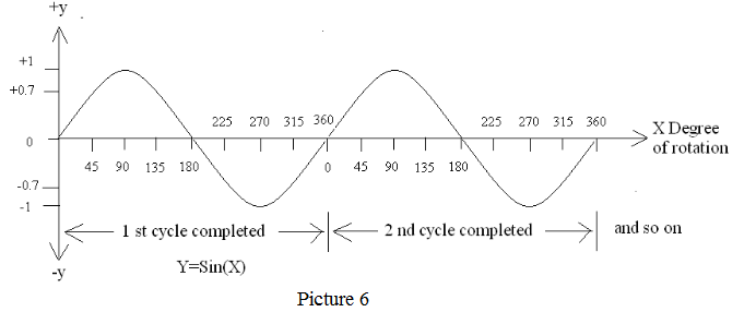
For angle C = 360 degree Sin ( C )= AB/OB= 0 (one cycle completed ). Since Sin (360 degree)= Sin (0 degree)= 0
Because they are at same position on circle. Then point B keeps continue to run and go through 45 degree again and so on. The cycles now displays on a X-Y figure. ( Picture 6)
700300
Now we change the X axis to time t scale for a 60 Hz sine wave which completes one circle in 1/60 second or completes 60 circle in one second. (Picture 7 )
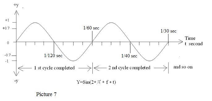
Hz is a frequency unit equal to how many circles completed within one second as the point B did. 60Hz means 60 cycles being completed in one second, some electronic hobbist would like to use cycles per second ( C/S ) , they even omit the letter S, for example 455 KC means 455 KC/S and this is equal to 455000 Hz. (yes, point B passed around the circle 455000 times within one second) However Hz is a formal engineering terms.
Now we can discuss the three important factors of sine wave.
1. Frequency – This is the speed of the wave describes how fast the point B moves, unit Hz (cycles per second)
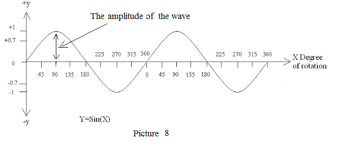
2. Amplitude – The peak value of the wave , it could be voltage (unit Volt V ) or current (unit ampere A )
See picture 8.
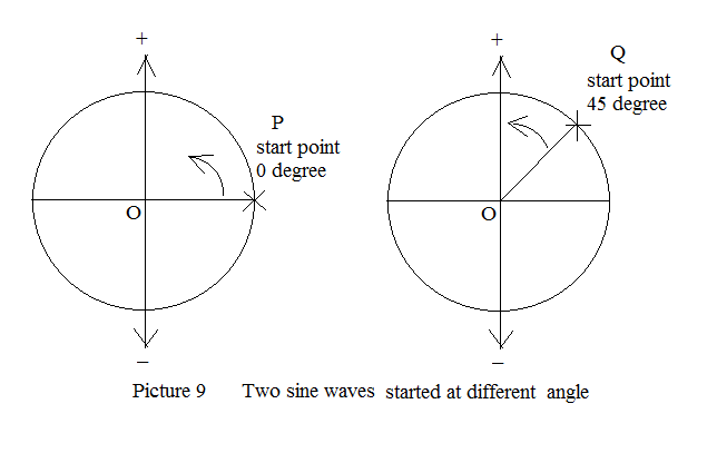
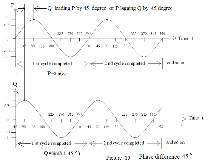
3. Phase difference – this is the most important factor for sound staging in two channel stereo Hi Fi systems. I saw very rare articles on the web pages talking about the relationship between phase difference and sound image sharpness. Think about two sine waves P and Q with same frequency and same amplitude , at a same moment, P started at 0 degree while Q started at 45 degree. ( see picture 9 )
In x y scale shows the phase shift , the sine wave Q reaches the maximum earlier than that of P by 45 degrees, see picture 10:

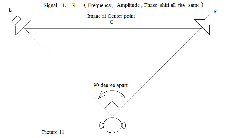
Phase difference is talking about the relative phase (angle) shift between two sine wave of same frequency. Two sine waves have same frequency, same amplitude and same phase ( means no phase difference or no phase shift ) are said to be equivalent to each other (same signal). A pair of speakers being put 90 degree apart in front of a listener, L and R were fed by equivalent sine wave forms , same signal . The experience tells us that the sound image will be focus at center point C, and as if there is no sound come from two speakers. See picture 11:
There is nothing new right ? We rotate the same set up by 45 degree see picture 12:
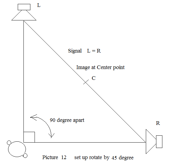
The listener also turn by 45 degree to fit in again, nothing will change , sound image still at center point.
Now, think about two equivalent sine wave signals feed into X and Y axis of a X Y coordination.
See picture 13, 13A :
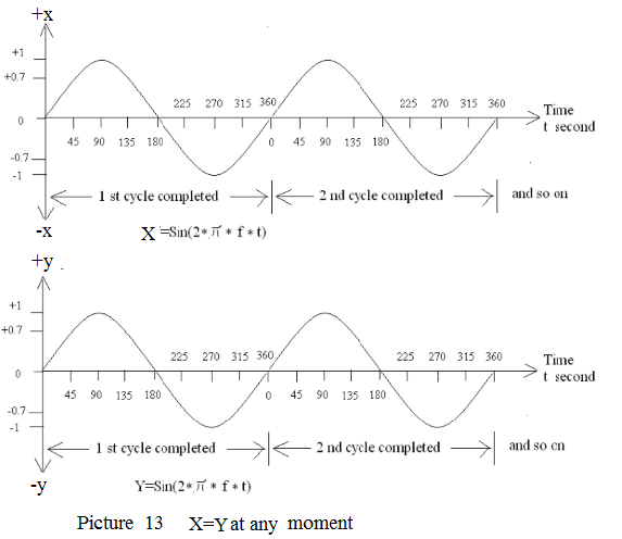
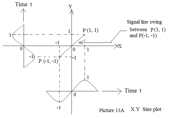
At time t =0 X=0 ; Y=0
At time t for 45 degree X=0.707 ; Y=0.707
At time t for 90 degree X=1 ; Y=1
At time t for 135 degree X=0.707 ; Y=0.707
At time t for 180 degree X=0 ; Y=0
At time t for 225 degree X= -0.707 ; Y= -0.707
At time t for 270 degree X= -1 ; Y= -1
At time t for 315 degree X= -0.707 ; Y= -0.707
At time t for 360 degree X=0 ; Y=0 .
One cycle completed and go on.
Now we plot the graph on a X Y coordinate figure see picture 14:
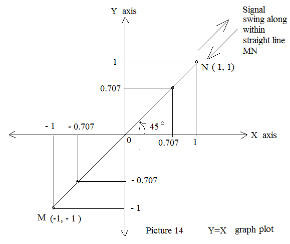
Actually this is a straight line MN, known as signal line, 45 degree from X axis, the signal swing between M (-1,-1) and N(1, 1). Think about the Y axis is Left channel speaker and the X axis is the Right channel speaker driving by same signal see picture 15 :
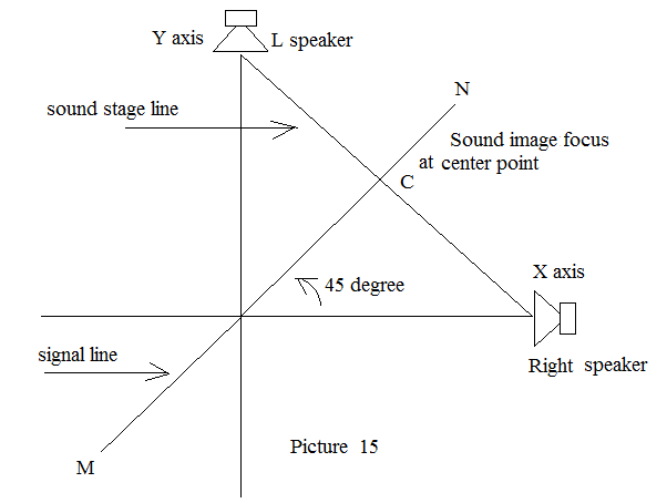
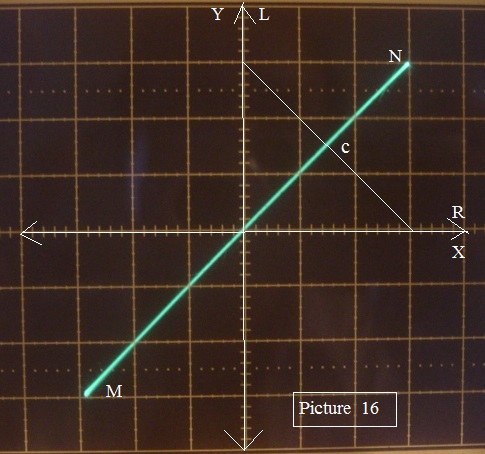
Draw a straight line connecting L and R speakers , this is the sound stage line , the inter section point with signal line MN is the sound image focus point C. Since X= Y at any moment , straight line MN will be 45 degree apart from both X and Y axis so as the inter section will equally cut the sound stage line and the point C set at the center. This is the mathematical solution to explain why the sound image will be at the center if equivalent signal to both speakers. Actually if same signal connected into an oscilloscope X and Y input will get same result see picture 16:
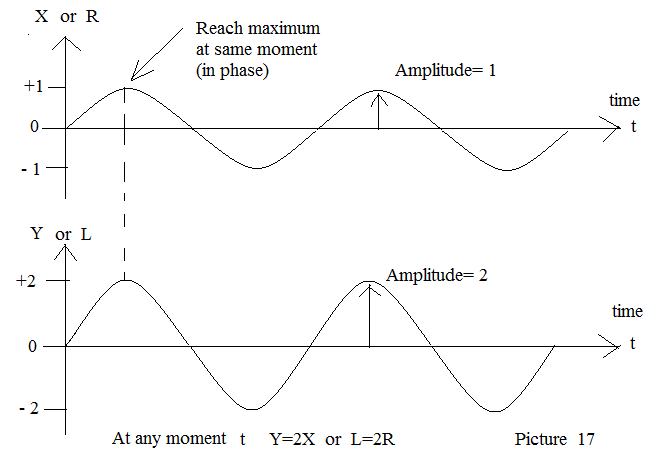
Now if we set Y=2X or L= 2R that means L channel is louder than that of R channel by 2 times (amplitude ratio = 2 ) , frequency and phase remain unchanged. See picture 17 :
Plot line MN for Y=2X or L=2R , it is still a sraight line 60 degree apart from X axis see picture 18 :
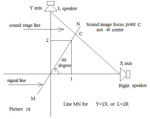
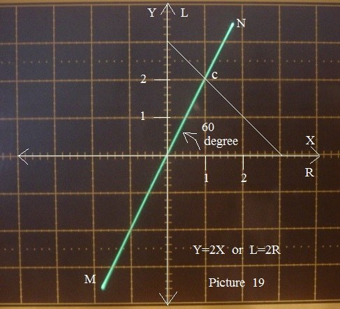
Now line MN of L=2R ( Y=2X ) is still straight line and 60 degree from X axis. Obviously line Y=2X will move the point C towards L speaker and no longer at center, the sound image also moved toward L speaker. See oscilloscope same result picture 19:
The different amplitude ratio between L and R will move the point C along with stage line. See picture 20 :
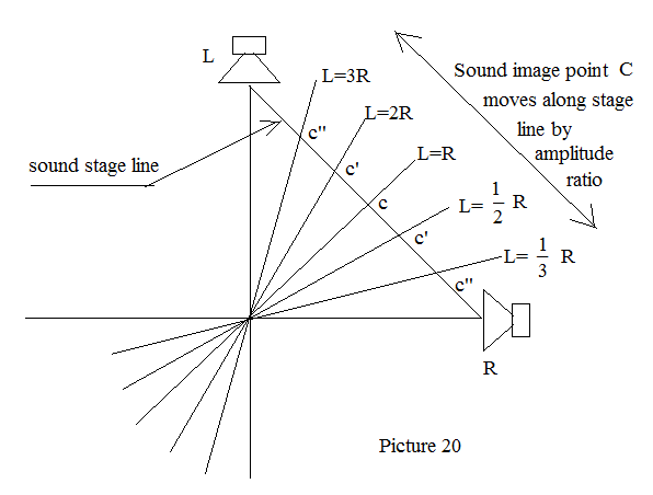
When we listen to a CD, the sound images are pre-designed by amplitude ratio rather than true musical instrument physical positions. The straight line on the oscilloscope display will point to the sound image direction if we put the scope on floor and top side faced to L speaker, this is helpful to monitor the pre-designed image position in sound reproduction process.
See picture 21:
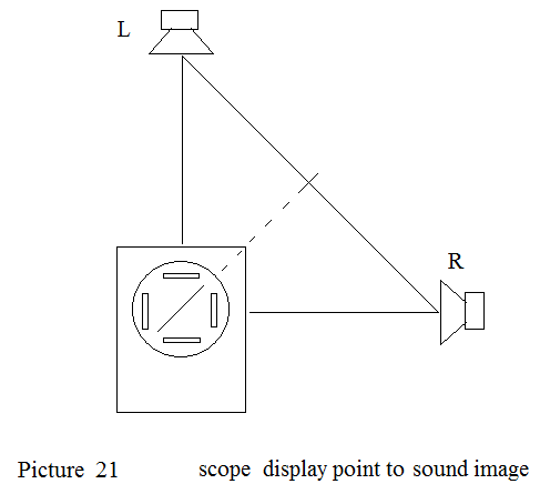
Remember that, amplitude ratio changes with no phase difference will create a straight line MN, so that the inter section with stage line is a point , the sound image will be a sharp point as well. Amplitude ratio stereo system is widely used in popular musics.
Now we go further to see the effect of phase difference between L and R channel. Let P and Q are sine waves phase shift 45 degree apart see picture 10 again:
P applied on X axis (R channel), Q applied on Y (L channel),
At time t =0, X 0 degree , Y 45 degree X=0 ; Y=0.707
At time t for X 45 degree , Y 90 degree X=0.707 ; Y=1
At time t for X 90 degree, Y 135 degree X=1 ; Y=0.707
At time t for X 135 degree, Y 180 degree X=0.707 ; Y=0
At time t for X 180 degree , Y 225 degree X=0 ; Y=-0.707
At time t for X 225 degree , Y 270 degree X= -0.707 ; Y= -1
At time t for X 270 degree, Y 315 degree X= -1 ; Y= -0.707
At time t for X 315 degree , Y 360 degree X= -0.707 ; Y= 0
At time t for X 360 degree , Y 45 degree X=0 ; Y=0.707 ( One cycle completed and go on.)
Now we plot the graph on a X Y coordinate figure, no longer a straight line but an ellipse see picture 22:
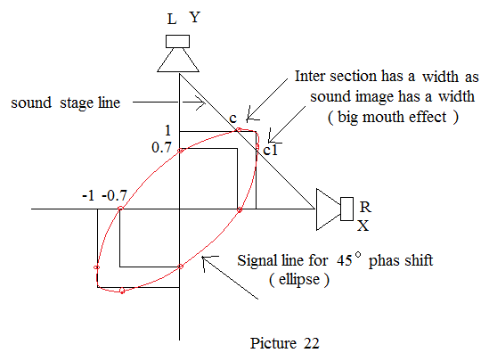
Now the intersection is no longer a point but a width. The sound image also spreads to that width and human ear will hear a large month singer. The oscilloscope shows the 6 dgreee phase difference result. (picture 23 )
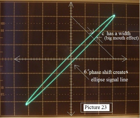
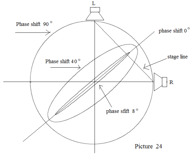
The worst case is 90 degree shift, signal line becomes a circle, sound image point spreads on whole stage line, 40 degree spreads almost one third of stage line, 8 degree shift causes a large mouth singer and 0 degree straight line creates an image point. See picture 24:
In general speaking, 1 to 2 degree phase shift does not affect the sound image much, but 5 degree or more will deteriorate the sound quality.
In most tube amplifiers, RC coupling do create phase shift especially near the turning frequency, think about the line signal goes through about 6 RC coupling while the phono input goes through about 9 RC coupling before reaches the speakers, 24db active electronic cross over caused 8 RC coupling more.
So many RC and transformer coupling as phase shift could not be avoided, but if L and R channel to be arranged to have same phase shift known as synchronization, the relative phase between L and R will be no phase difference , the straight signal line MN maintained as well as the sound image.
See the stereo tube voltage amp set up , a coupling capacitor 0.1 uf with a grid resistor 100K will create about 7.5 degree phase shift at 120Hz. If both channel create 7.5 degree exactly is known as synchronization and there will be no problem in sound image.
See picture 25 :
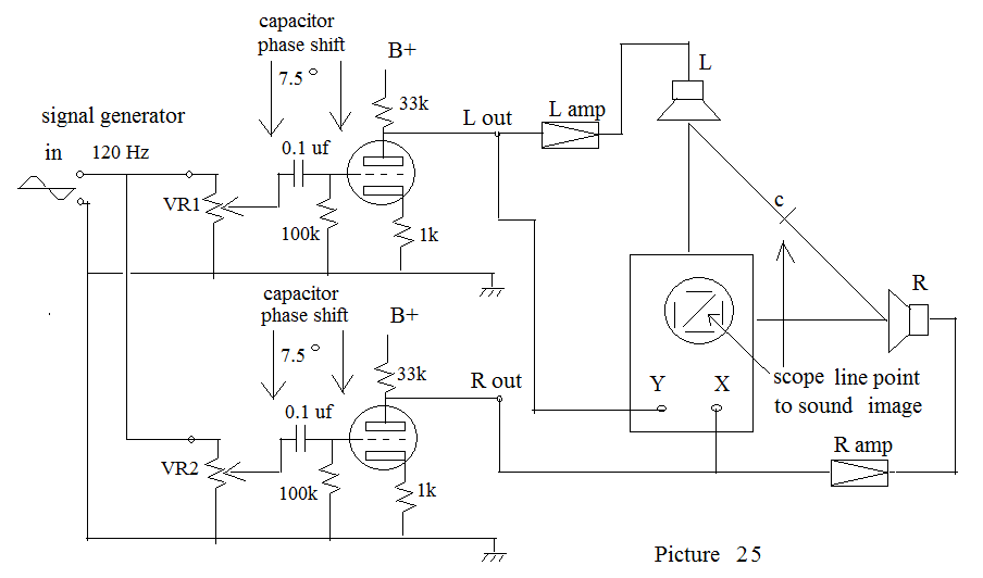
In this case VR1 and VR2 adjustment will move the point C along the stage line but the +/- 10 % of 0.1 uf cap and 100K resistor will create phase difference.
I try to add a 0.02 uf to one channel to simulate +/- 10% capacitance error the scope shows an ellipse about 1.5 degree, think about accumulation of 6 to 7 RC couplings the situation could be serious.
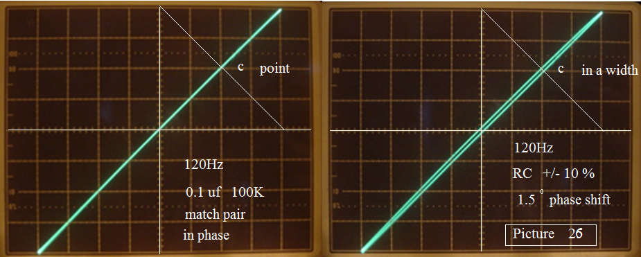
Match pairs 0.1 uf and 100K for both channels will ensure synchronization, I strongly recommend 1% match RC pairs in tube amp coupling circuit.
Picture 26 compares between 0.1 uf , 100K match pair and +/- 10% error capacitor signal line results :
Thank you for visiting!