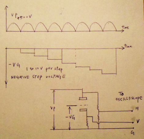
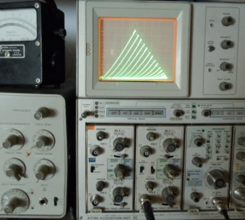
A tube curve tracer can display the comprehensive information of the tube status in graphical mathod. This is almost telling everything we really want. Commercial tube curve tracer is expensive but a simple home built curve tracer is not too far difficual. In late 1970 the TTL (transistor_transistor logic) and CMOS ( compelmentary metal oxided semi_condustors logic) helps a lot to achieve the waveform requirements for curve tracing circuit, and then greatly reduces the cost. The following picture shows the working principle of a tracer, a Vp about +500V applied at plate while the negative step voltage applied at the grid. The divider ledder resister gives a voltage directly proportional to Vp and a cathod resistor voltage drop is also directly proportional to plate current Ip. Both signal feed to H and V input of an oscilloscope to display the curve, that is simple right ?
See picture:
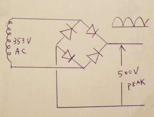
Ok, the +500V plate voltage is easy job, a 500/1.4142= 353V AC with a full wave rectifier without any filter capacitor or choke can do.
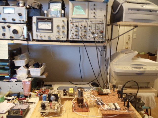
See picture :
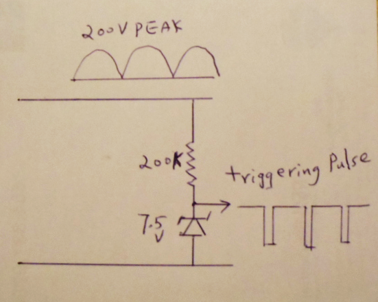
The -VG step voltage is a bit more difficual, firstly we want a triggering signal to tell the step generator to change the step, and this changing should be synchronious with +500V Vp, we use a AC full wave rectifier again without any capacitor, a 7.5 volt zener diode in series with a 200Kohm resistor can give the triggering pulse,
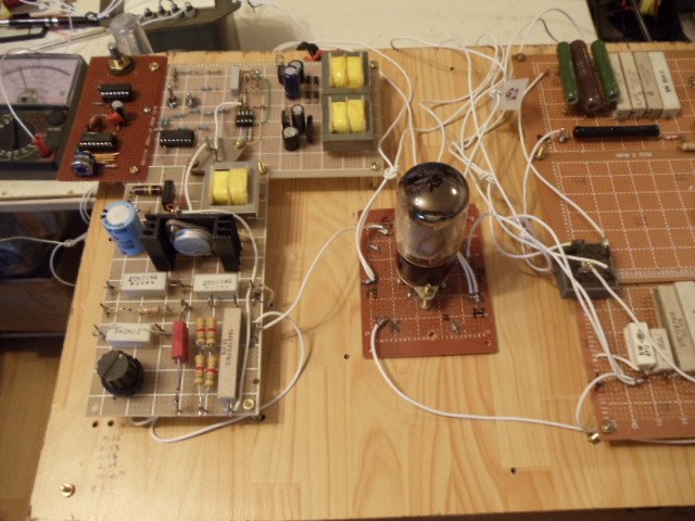
see picture:
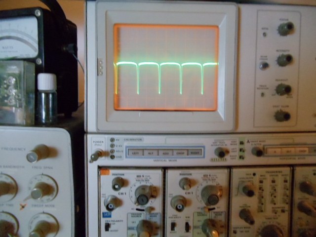
The actuall pulse on scope, see picture:
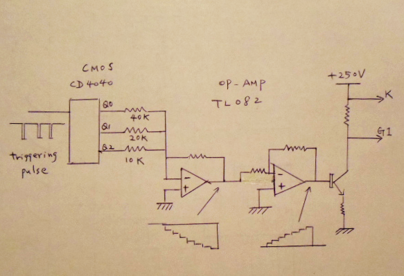
Now we use a CMOS CD4040 binary counter, the out put Q0, Q1 AND Q2 will change once the triggering pulse arrives. Three weighted resistors of 10K 20K and 40K connected to Q1 Q2 and Q3 and join together to negative input of op_amp TL082, the TL082 output gives the negative step voltage, the op_amp output drives a transistor to get a 0.5ma per step collector current, the voltage drop at collector resistor Rc is the final output and connected to the cathod and no.1 grid of the tube under testing.
See picture:
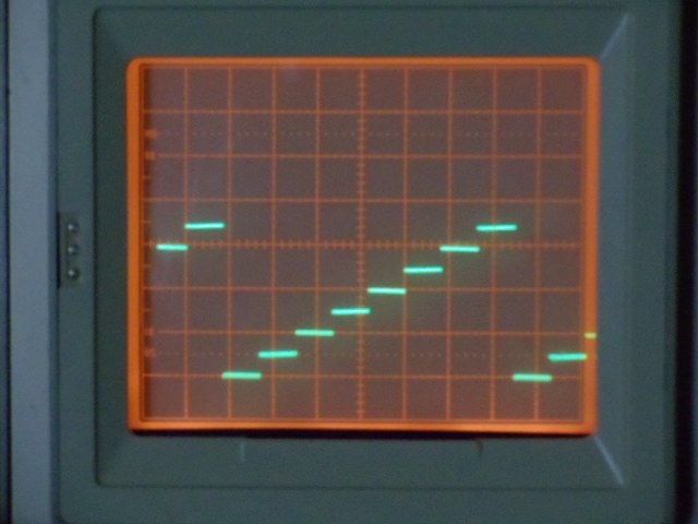
The actual grid driver output, see picture:
The heater supply and G2 voltage supply for pentode, tetrode is simply included in the tester, of cause triode no need G2 supply.
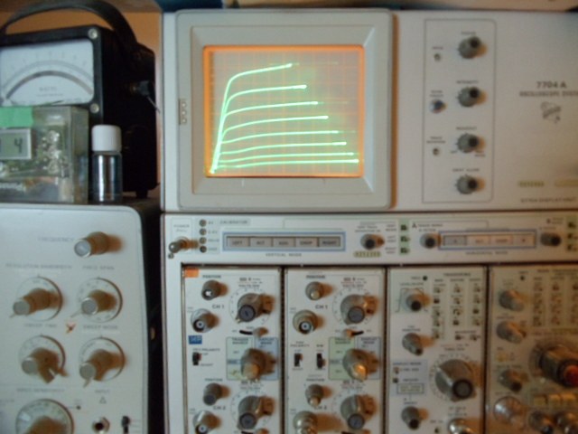
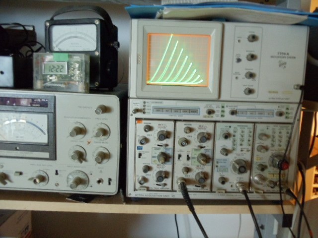
See a RCA 245 under test :
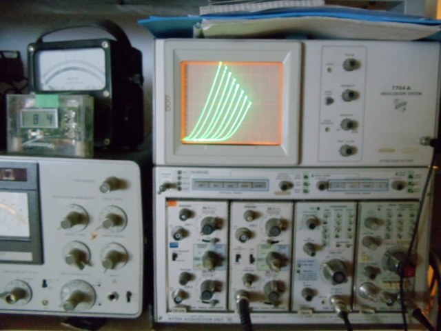
See a 5881 under test :
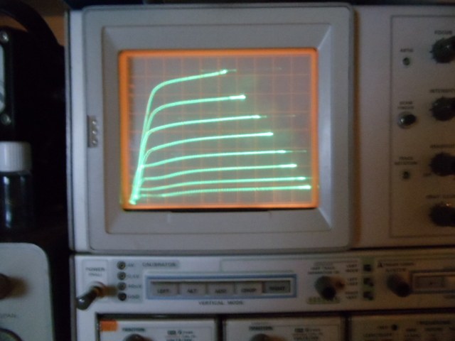
See some testing result examples :
Thank you for visiting!