There are two major types of tube testers:
- Simple emission tester
- Dynamic mutual conductance (GM) tester
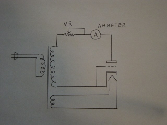
- The Emission Tester – is simple that the grid of the tube under tested is connected to the cathode itself then only plate and cathode being left, somewhat likes a diode and then connected series with a variable resistor and ammeter to a known AC supply. It works exactly as a rectifier diode, refer to roll chart the ammeter reading and variable resistor setting will give the test result, it is simple to explain see picture:
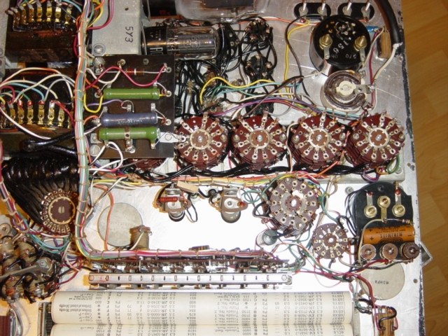
- Dynamic Tester – the most dynamic testers have seven selectors set for the different type of tubes. They seem complicated, but they are merely connectors to fit plate supply to a plate, grid supply to a grid…etc. Because a different type of tube has different pin layout.
For example RCA UX245 roll chart setting “1432000” means the first selector being set to 1, second set to 4 and third set to 3 and so on. It is convenient and fast to fit different tubes according to chart setting. If we can connect the pin manually these selectors can be taken away and will not affect the test result.
The heart of dynamic tube tester consists of four major components:
- Phase alternating plate supply
- DC grid bias
- AC grid excitation
- Meter network
Also, there is filament supply, push to test button and protection fuse but these do not directly affect the operating principle. Before we go ahead, we have to know the triode operation first.
.
.
The triode operation is simple, a +Vp applied on a plate to cathode and a -Vg applied on the grid to cathode, both of these voltages can affect the plate current, Ip. Now we have 3 variables, all of these 3 variables are just fit into a three-dimension graphic, please imagine the tube operating area likes a piece of cloth floating in a three dimension space:
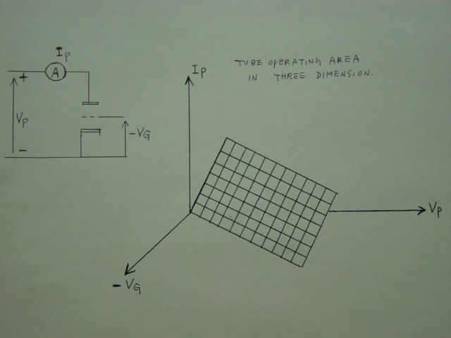
This three-dimension graphic can be represented by two dimension graphics in 3 aspects, the first one is front view, known as the “Plate Characteristic”:

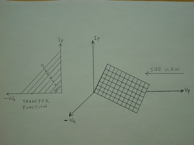
The second is side view, the “Transfer Function”:
The third one is top view, the “Constant Current Characteristic”:
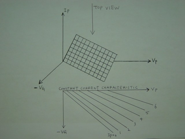
Ok, it looks a bit confused, but don’t worry, all of the so-called plate characteristic, transfer function, and constant current characteristic are talking about the SAME thing. To understand the tester principle, the plate characteristic graphic is the easiest one.
The heart of dynamic tube tester consists of four major components:
- Phase alternating plate supply
- DC grid bias
- AC grid excitation
- Meter network
Now we can start at phase alternating plate supply see picture:
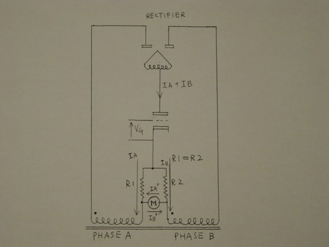
The plate supply winding divided into two coils and make the dot notation phase relationship. So that when phase A (IA) is working phase B (IB) is not or vice versa.
.
.
IA and IB go through the plate and cathode alternatively in the same direction.
R1, R2 and DC meter M formed meter network, where R1=R2, IA goes through R1 and IA’ goes through meter M at phase A working, IB goes through R2 and IB’ goes through meter M at phase B working.
IA and IA’ have a directly proportional relationship, IA’ increases as IA increases. IB and IB’ do the same.
AS R1=R2 so that IA’=IB’ but in opposite direction and then algebraic sum is zero so that DC meter M pointer will not move:
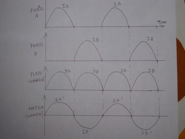
We examine the plate current, to make it simple now we consider VG=0, no grid bias, and no grid excitation:
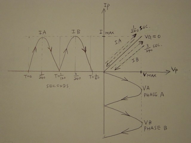
At time=0, SEC IA starts working and reaches I MAX at time= 1/240 SEC goes back to zero at time= 1/120 SEC.
At time= 1/120 SEC IB starts working and reaches I MAX at time= 3/240 SEC goes back to zero at time= 1/60 SEC.
Then one A+B cycle completed. This example shows that the plate current moves up and down twice along with the VG=0 curve in PLATE CHARACTERISTIC (front view graphic ).
If we applied -1 V dc to the grid, the plate current waveform will be similar but it will move along with the VG= -1V curve in PLATE CHARACTERISTIC graphic, and so on.
Now we can consider DC grid bias and AC excitation added together applied to grid and cathode, a -5V DC connected in series with a 10Vpp (3.54V AC RMS) transformer winding, the grid signal will move between 0V and -10V:

We examine the plate current again, with DC grid bias and AC excitation:
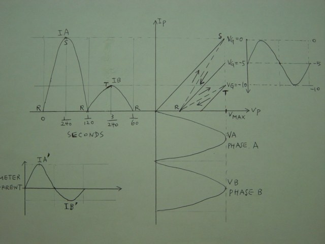
At time=0 SEC, IA starts at point R and reaches IA MAX at time= 1/240 SEC (point S), goes back to zero (point R) at time= 1/120 SEC.
At time= 1/120 SEC, IB starts at point R and reaches IB MAX at time= 3/240 SEC (point T), goes back to zero (point R) at time= 1/60 SEC.
Then one A+B cycle completed. This example shows that the plate current moves up and down along with the dotted line from point R to VG=0 and VG=-10 curve alternatively in PLATE CHARACTERISTIC(front view graphic).
The IA max is larger than IB max, this is because AC grid excitation affects the grid signal:
When IA reaches its maximum VG= 0V
When IB reaches its maximum VG= -10V
.
.
The meter current IA’ and IB’ are not equal now and the algebraic sum is not zero, the meter needle will move, and the moving angle is directly proportional to the area of triangle RST. This area is also directly proportional to the mutual conductance GM of the tube under test, actually the angle in which the needle moved is the mutual conductance itself. See, we get it and have fun!
The errors of tube testers:
- Threshold error
The tube begins to conduct current at point R in which Vp has already built up to a value called threshold voltage. This made the current waveform of IA and IB is not purely sinusoidal, the design of meter network is based on sinusoidal and average voltage transformation, this will introduce an error about 3%. - The plate supply voltage drop (power regulation) error. When IA or IB reaches its maximum value the plate supply voltage will drop about 5%, this will introduce an error of about 10% to 15% depending on which type of tubes. Most of the meter networks have been designed to compensate these errors, only well calibrated and correct setting operated testers can give accurate results.
Operating limitations
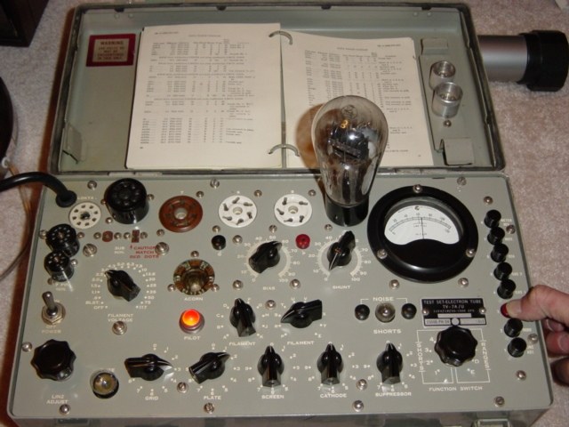
For most testers, the phase A and phase B maximum supply voltage is fixed. For example, HICKOK 539A and TV-7 are fixed at about 200V max. But the tube true life operating point is about 275V for 245, 250V for 2A3 and 350V for 300B. All these tubes will be tested only at 200V MAX and is assumed to be similarly good at 275V or higher.
A plate current(Ip) static DC amplifier test under tube manual provided working voltages (Vp, Vg) is strongly recommended to confirm the tester result(in true life).
Thank you for visiting!