The heart of Marantz 7 M7 line amp is a two common cathode stage with negative feedback followed by a cathode follower.
The design is simple with few components, but both the tone control and filter circuit deteriorates the sound details a lot also so many switch contacts inserted further down grade the sound quality , clone results from different DIYers varies.
The circuit is simple, but the result could be great if built correctly.
The B+ supply voltage seems random but actually is carefully selected to handle up to +20 db signal peak at very low frequency end.
The 500K trim pot works for better S/N ratio but also cutting down the high frequency response as a side effect.
In an original M7 machine, there is no any B+ supply stability arrangement and too much switch contacts inserted, the over all result is a bit foggy sound and not enough detail in midrange, also a bit weak at high frequency end.
The heart design is supper to see whether we can dig the treasure out or not.
Some Diyers agree a point of simplest is the best, if this is always true then a single triode common cathode amp could dominate . But the fact is different designs share the market in competition.
Actually the famous Mertisse Reference line amp has the similar philosophy with M7 .
How can a line amp of two common cathode stage with negative feedback plus a cathode follower win a position in the high end world for decades ? Let’s go and see.
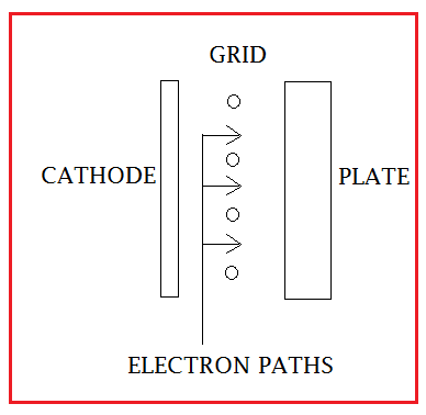
The electron flow inside a triode see picture:
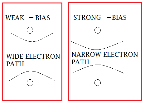
The negative bias at grid wire creates an electric field near around the grid wire, and this electric field size varies as bias changes , the result is changing the electron path width between grid wires as well as plate current, see picture:
Due to the mass of electrons the final value of plate current responses to bias changing will not be reached immediately after the bias changed. There will be an overshoot before the final value , an appropriate negative feedback arrangement will improve the over shoot a lot, see picture:
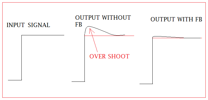
Please note the situation is intentionally exaggerated to clearly show the case.
In case of no NFB, for low frequency the bias changing is slow enough to be followed so that there will be fine, for high frequency side the input and output stray capacitance will automatically correct the over shoot and even further turn down the high frequency response. So that the overall result is an excellent base, a too bright mid and a bit darken high.

This end result often can be find in single triode line amps, even a cathode follower added, but not in power amps , this is because the line amp output signal will be further amplified whilst the power amp is almost the last stage to the speakers.
So that the theory of non negative feedback applied at single end tube power amp is correct, but for preamp the story might be different. I understood some DIYer prefers non NFB triode preamp for the attractive bright middle human voice as a special taste.
The negative feedback circuit compares the output and input signal and corrects the overshoot far before the peak wave form comes, in high frequency side, NFB also detects and corrects the under shoot to maintain a perfect response. The NFB loop is short and the response of 12AX7 is fast enough to cover up to over 100KHz and fulfills the high end standards.
The M7 NFB loop was intentionally designed not including the cathode follower to get a shortest loop path so that it is fast enough for transience response. Any similar line amp design NFB loop including the cathode follower could not get a better result as the response speed slows down.
The only shortcoming of original M7 line amp is a +6 db response at about 3 Hz at output point. This problem was overcome by correct choose the B+ voltage and plate operating point. Yet +6 db in 3Hz might be welcome for increasing low punch, no longer a shortcoming.
A well fine turned DIY M7 machine stuck to this rules could become one of the best tube line amp in the world.
Please see the original M7 design with 30Hz high pass filter for record turntable rumbles as in 1960s high end turntable was not popular as to day. Again the 5000Hz low pass filter is for tracking dust noise from play black plastic records. A 30Hz to 5000Hz response is very similar to that of AM broadcasting. So that bypass switches can override the filters to handle better quality sound sources.
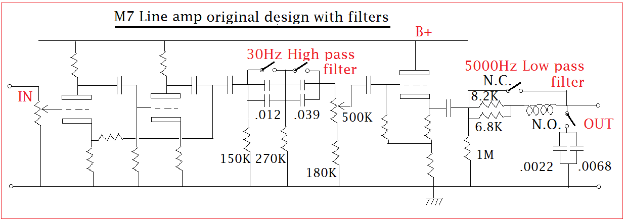
Nowadays we no longer need these filters please see picture:
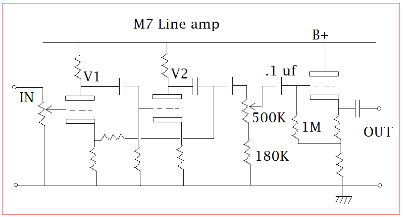
The overall gain of V1 and V2 is about 18 , the 500K trim pot works with 180K will give a 0.632 gain when setting at the center point , and the cathode follower gain is 0.97.
18×0.632×0.97= 11
This matches the line amp standard gain of 10.
By examine the trim pot circuit: (500K+180K)/4= 170K
If the input circuit and grid to cathode stray capacitance of the cathode follower reaches 30 pf , a typical value, the high frequency response will be about 30KHz – 3db. It seems ok.
But if we don’t mind the overall gain 18×0.97= 17.5 , we could override the 500K trim pot and achieve a high frequency response of 100KHz -0.6 db.
I suppose most of the DIYers would choose override the trim pot, please see picture:
This is the original designed component value of M7 line amp, if we follows these values could get a very good result: 10Hz to 50KHz +/- 0.5 db or better, trust me, this is very true.
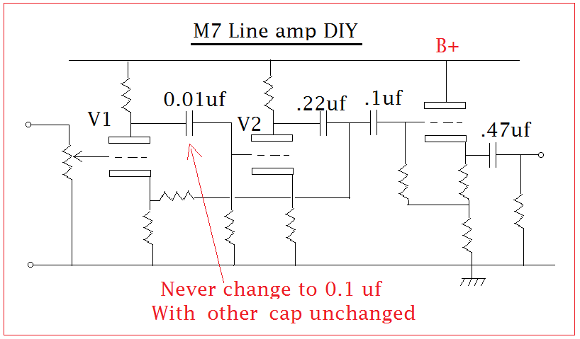
I understood most experienced DIYers didn’t feel comfortable with the 0.01 uf coupling capacitor at V1 plate, copes with 1M grid resistor the low frequency -3db point is about 16Hz, too high for high end purpose. Yet some DIYers would like to modify the machine for better performance, then enjoy the excellent sound with satisfaction. The most common suggestion is using a 0.1 uf to replace the 0.01 uf cap so that the -3 db point will be 1.6Hz, much better. But, don’t do this please , it will ruin the machine in both high and low frequencies.
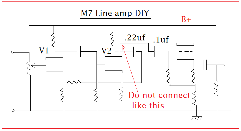
To clone a M7 line amp , NEVER do the following two things:
- Never get the output signal directly from V2 plate so as to avoid two capacitors in series as well as saving the signal path, because this connection might overload the cathode follower , see picture:
- Never change the 0.01 uf capacitor to 0.1 uf with other capacitor remains unchanged. This will make V2 plate See picture:
The V1 and V2 form the heart amp , high speed negative feedback loop expends the wide range frequency response, the cathode follower provides impedance matching, high input impedance doesn’t burden the heart amp (very important point )and low output impedance could fight for signal cable stray capacitance to maintain high frequency driver capability. Further more, the cathode follower could improve horn driver metallic sound so M7 is good for Altec 288/ 290 and Tannoy drivers because the mid range under control not too bright. A perfect design.
Key point : The M7 line amp secret formula
There are two RC networks in the heart amp :
- C1, R1 are forward RC network
- C2, (R2+R3) are feedback RC network
See picture:
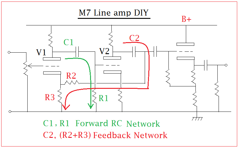
The RC time constant of forward and feedback network should be equal to each other for excellent performance , so that the secret formula is :
C1 R1 = C2 (R2+R3)
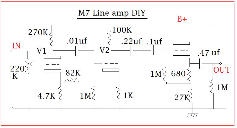
If we choose 0.1 uf as C1 then:
(0.1 uf)(1000K) = C2 (82K+ 4.7K)
Then:
C2 = (0.1 uf)(1000K)/ (82K+ 4.7K)
C2 = (0.1 uf)(1000K)/(86.7K)
C2 = 1.15 uf We can use 1.2 uf
That means if we change C1 to 0.1 uf, we have to change C2 to 1.2 uf otherwise RC network out of balance causing frequency response out of balance as well.
Please see original M7 circuit:

R2 = (4.7K+82K)// 150K// 270K// (500K+180K) = 42.7K
Where C1 R1 = C2 R2
( 0.01 uf) (1000K) = C2 (42.7K)
C2 = (0.01uf) (1000K) / (42.7K) = 0.23 uf The M7 designer uses 0.22uf
I suggested the final version of M7 line amp DIY :

The V1 open loop gain :
270K // 1M + 80K + (4.7K X 101)
= 212.6K +80K + 474.7K
= 767.3k
V1 gain = 100 (212.6/767.3)
= 27.7
The V2 open loop gain :
100K // (82K +4.7K ) + 80K + (1K X101)
= 46.4K +80K +101K
=227.4K
V2 gain = 100 (46.4/227.4)
= 20.4
A = V1, V2 open loop gain
= 27.7 x 20.4
= 565.08
B = 4.7K / (82K + 4.7K)
= 4.7/ 86.7
= 0.0542 (known as feedback factor)
Close loop gain = A / ( 1 + AB )
= 565.08/ (1+ 565.08X 0.0542)
= 565.08 / 31.62
= 17.87
Over all gain = 17.87 X 0.97
= 17.33
Frequency response :
5 Hz to 50KHz +/- 0 db
5 Hz to 100KHz – 0.6 db
5Hz to 300KHz -3 db
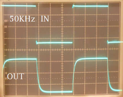
Square wave response :
10KHz output 6 Vpp
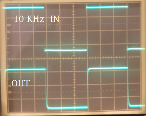
20KHz output 6V pp
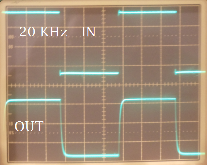
50KHz output 6V pp
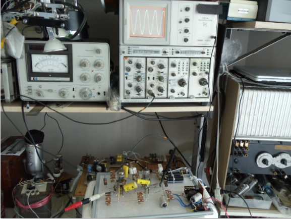
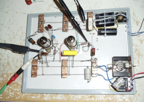
Testing on experiment board.
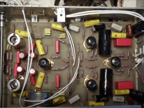
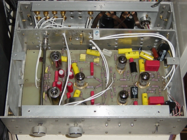
The actual machine building
Power supply arrangement:
For preamps, stabilized B+ supply is a must or bad performance even good design.
Those close loop voltage stabilizing circuits are slow, any active power supply claimed fast becomes slow motion in front of 300KHz.
A very simple method is to use Zener diode, 40 pcs of 7.5V 200mW Zener connect in series will get 300V. 7.5V Zener diode has good sounding.
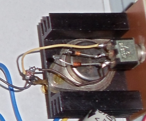
An example of 7.5V Zener diode array :

Filament supply strongly recommend DC stabilize using 7812 TO-3 metal package with heat sink.
Power supply :
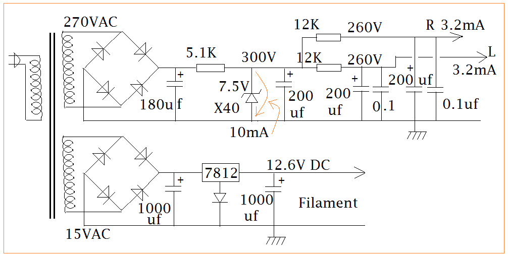
Two 12K resistor use wire wound type better, 7.5V Zener and 12K try different brand name to fine tune the sound. The 200 uf capacitor is carefully selected so don’t go away from 180 to 220 uf range. Two 0.1 uf bypass cap use high quality capacitors. V1, V2 and cathode follower share a same B+ supply is intentionally arranged not for saving component budget but for good sounding.
In the line amp , all coupling capacitors have to use high quality component, I would not suggest any brand name but they should have the loss factor equal to or better than 0.0005 , the bottom line. Also the 1960’s old type 12AX7 or ECC83 strongly recommended.
If we change the 82K resistor to 47K , 1.2uF capacitor also change to 2.2uF, the overall gain will be about 10, could give a better sound, worthwhile to try.
Point to point wiring gets better sound, print circuit board is more convenience to build, also neat component layout for visual effect or shortest path for excellent sounding is a personal choice, enjoy.
Thank you for visiting.
Hi I’m keen to build this Marantz M7 but the parts list is missing from your post could you please put a parts list that states how many watts and volts of the resistors and capacitors. Thanks.
Is there a parts list for this wonderful pre?
Thanks very much
Hello, thank you for this very interesting and informative article. I notice two Marantz 7 clones that have circuits like those on your post (Music Angel and Mable/Douk Audio). However, neither compensates for the change of the 0.01µF capacitor to 0.1µF in the way you recommend. I wonder if you think these preamps would be improved by following your suggestion, or if you think these circuits have corrected the problem in some other way. Thanks.
What an awesome project! Indeed, I would be interested in the list of parts you used, do you still have it?
hallo..
a perfect analyzing of this little amp…
gr jan…
Here is a design feature seldom discussed: Cathode follower has cathode voltage of probably more than 100 V. (I haven’t measured it) This means there is large potential between heater and cathode. Maximum spec for 12ax7 is 180V. Consider filament circuit to float the heater of V3 above ground. Original M7 design wires heaters in series which puts V3 heater 12.6 above ground. Not a lot but it helps. ARC SP3 has special circuit for heaters of CF tubes which floats them 400v above ground! Note: B+ of SP3 I very much higher than M7. .
Excellent analysis. How about a similar project for phone stage or M7 …. ? Thanks!
Thanks so much for posting this! I really appreciate people as yourself who have an enormous wealth of knowledge in tube audio going back to the time prior to it’s demise with solid state coming on the scene. I’ve been assembling parts for an M7 phono preamp build including tone amp as in original design but without the hi and lo filter sections and selectors. Articles as you’ve written here helps greatly in parsing out the bits and pieces we need to avoid making wrong choices in our remaking of classics as the Marantz model 7.
Thank you for a very interesting article! I will try most of your suggestions on a kit I will buy on Ali, the Zero Zone PRT07B, but I may just leave the regulated PSU part as is on that board, to start with.
Thanks for the detailed analysis of this line amp Terry. But I have trouble following some of your calculations, particularly for the open loop gain stuff. What are those 2 numbers 80 and 101?
Regards and keep safe.
Other variant is possible also
It is the amusing answer
Your opinion, this your opinion
У Нас скидки круглый год!
HoOkAh MaGic наш официальный бренд
Набрав в поисковике Вы можете посетить наш сайт
и возможно приобрести кальяны и всё для них.
Персональные скидки
Строго 18+
В пределах Москвы вы получаете свой заказ в течение 24 часов с момента заказа. Доставка в регионы России и страны СНГ осуществляется в минимальные сроки транспортными компаниями. Что касается доставки в страны мира, то это займет сроки от 1 недели. Сотрудничество с нами позволит вам приобрести кальяны оптом в любом городе России в минимальные сроки.