Discussion and test of single-ended output transformer
The single-ended output transformer is an iron core plus primary and secondary coils. The primary to secondary turns ratio is the voltage ratio. The square of the primary and secondary turns ratio is the impedance ratio. The inverse ratio of the primary and secondary turns is the current ratio. It looks very simple. Let us see if this is the case.
The output transformer is composed of a copper part (winding) and an iron part (iron core). Both parts have an effect on the sound. First, the iron core is an alloy mainly composed of iron, nickel, cobalt and silicon. (矽) and other components, different components have an impact on the magnetic properties and then affect the sound effect. The proportion of high-quality transformer core alloy and processing details are trade secrets, not easy to know, but they are inseparable from the basic principles. The transformer core is rolled from a steel ingot to a thickness of about 0.25 mm to reduce the eddy current effect. The punch is then punched into an EI type, and also rolled into a round shape and then cut In two halves into a C type, commonly known as C core.
Please see picture:
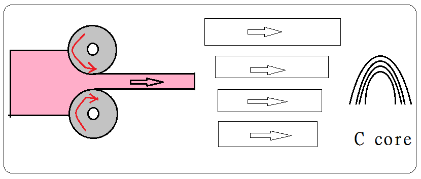
The processing is divided into cold rolling and hot rolling. Because of the high temperature, the hot-rolled steel sheet is still melting and has no directionality. Therefore, the hot-rolled steel sheet is more suitable for EI type because the magnetic flux will be deflected by 90 degrees in the EI shaped steel sheet. Because the temperature of the cold-rolled steel sheet is low, the fluidity of the molecule has been weakened, and it can only be formed in the direction of rolling, which is more directional, so the cold-rolled steel sheet is more suitable for the directional magnet flux as C core. Because the magnetic lines of force are moving in the direction of the C core steel sheet, please see the figure:

Because there is no magnetic line 90 degree deflection relationship, C core generally works well. So in recent years, C core core is used to make single-ended output transformer, and later DIY has an illusion that EI is not good enough, C core will not be wrong, forming a market point of tracing the C core and ignore the EI.
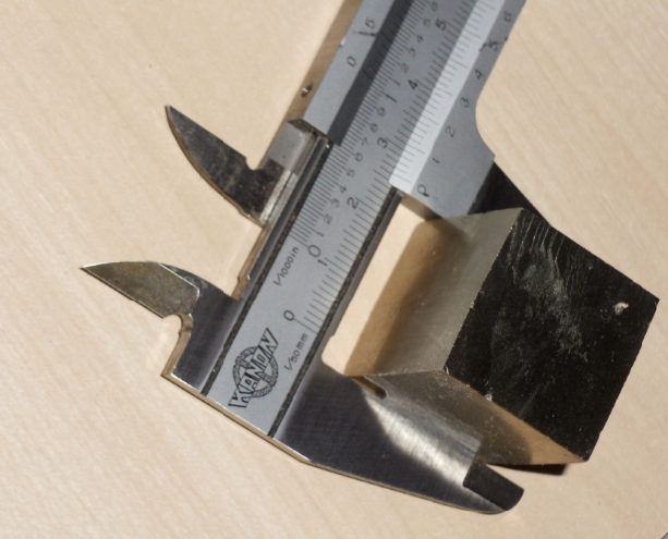
In addition, the frequency response of the core, regardless of the winding, the metal is composed of crystals, the shape of the crystal is determined by the molecular structure of the alloy, the size of the crystal is determined by the speed at which the melting temperature drops to the condensation temperature, and slower the rate of decline, The larger the crystal, the faster the rate of decline, the smaller the crystal, the temperature drop on the crust can be hundreds of thousands of years, and the length of the crystal can reach one meter. The figure below shows a metal crystal with a side length of 25 mm in the earth’s crust for tens of thousands of years temperature drop is formed:
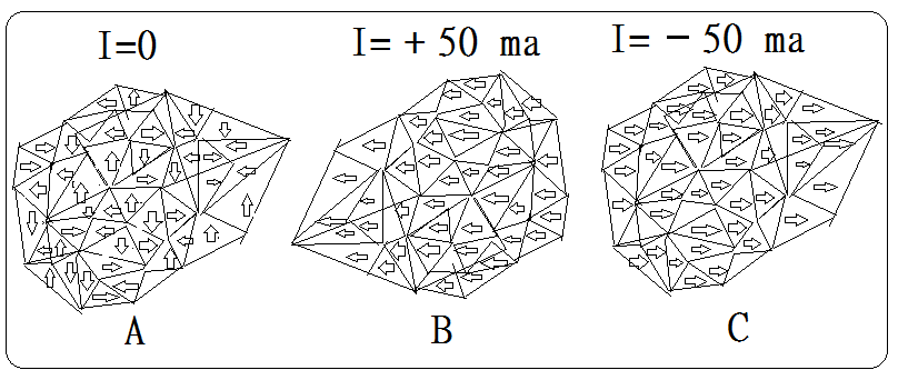
In the factory, the melting temperature of the core material drops to a condensation temperature of usually several to ten hours to control the size of the crystal in the micro meter range. Please note that the temperature is controlled to make the size of the crystal and the cold rolling is two different work. The most extreme example is that the temperature drops by one million degrees per second to form a nanometer-scale crystal, called an amorphous alloy. It is said that the high-frequency response is excellent because the smaller the crystal, the smaller the mass. High-speed magnetic jitter is easy to keep up with the winding high-frequency signal. The output transformer of this alloy has a high-frequency response of up to 100KHz, while the output transformer of a micro-meter scale crystal has a high-frequency response of about 60KHz to 80KHz. This is the highest response frequency of the core. The winding is independent, that is, the highest magnetic jitter frequency of the core crystal body. No matter how the winding is obtained, the response exceeding this highest magnetic jitter frequency will not be obtained. The following figure A shows that the winding has no current, the molecular magnetic distribution is not oriented, and B is positive. Current magnetization, C is reverse current magnetization:
Since the smaller the crystal, the smaller the mass, the higher the high-frequency response, and the use of an amorphous alloy (Amorphous alloy) to make the output transformer suppose will do, but in the sense of hearing, amorphous Amorphous alloy output transformer high frequency bright enough but low frequency sense is insufficient, medium frequency is not thick enough. whilst the output transformer of micro meter crystal is well averaged, medium frequency thickness and low frequency are good (related to hysteresis characteristic curve), high Frequency can also reach 50KHz is good enough, and finally look at personal choice. Generally speaking, the winding itself has no upper frequency limit, the only issue is stray capacity makes the high-frequency response rolls off at 6 db octave. Even so, its operating frequency is still much higher than the iron core, so the high frequency upper limit of the output transformer is determined by the characteristics of the core. To know the technical specifications of the transformer, the first thing to do is to measure the highest response frequency of the core.
.
.
In the 1940s to 1970s after the Second World War, it was the golden ages of vacuum tubes. The demand for a large number of output transformers led to the development and production of high-quality silicon steel iron cores. In the late 1970s semiconductors industrial applications successfully eliminated the vacuum tube , the transistor amplifier was popular, and the demand for high-quality output transformer core steel sheet was reduced, which caused the output transformer iron core material research development stopped.
In the 1980s, high-power high-speed semiconductors have become popular, high-power switching power supplies have high efficiency, low cost and high demand (for industrial Internet servers), working frequency requires 50Khz square wave, or 250Khz sine wave, industrial Internet server upgrade very fast, large Power switching power supply demand is then large.
Since the 1980s, most Iron and Steel manufactures has invested a lot of resources in the development of Ultra-thin silicon steel C-core iron chip for high-speed high-power switching power supply, in order to improve the frequency response, use a smaller volume of nano meter grade crystal, frequency response up to 300KHz sine wave, also known as Amorphous Cut Core, switching power supply with C-core core design has a very high frequency response, that is, even using ordinary power transformer method to make winding, the frequency response could still be easy to reach more than 300KHz, but the low-frequency response and distortion are not keeping in considerations very much. Please google search “Switching power supply transformer c core” for detailed information.
The demount of high-quality output transformers is decreasing day by day, and the steel sheet production plant in the 1990s is reluctant to take orders because of high technical requirements and low order quantity, which is not economical. High-quality output transformer production plant after using up the iron core inventory, the production has been discontinued. Some manufacturers simply sell the brand, some moved to Southeast Asia for production, the quality is not guaranteed. The original West Electric WE 171A, Tango X10SF and Tamura F2013 are high-level single-ended output transformer all has been discontinued, and the inventory has been sold out ten years ago. Now it can only be bought at a high price. The following picture is Tamura F2013 (single-ended flagship):
Modern output transformer production plants use standard specifications of iron chips such as M6, Z11, Oriental Hi B, etc., the effect is not bad. A good output transformer is determined by two sets of data, one set is hard data, that is, physical characteristic data, and there are physical standard. The other group is soft data, that is, the ear feeling data, which cannot be measured, only depending on the human hearing and cultivation. Personally I think that hard data is like the foundation of the building. Soft data is like the upper level of the building, if There is no good enough foundation. The beautiful building will collapse. That is to say, good sense of hearing is based on technical data of excellent physical characteristics.
.
.
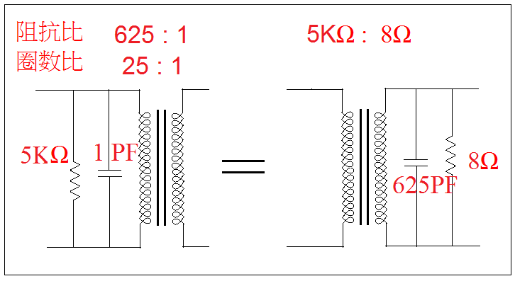
To measure the highest response frequency of the core and other important data, a mathematical model called an ideal transformer is used. Its primary and secondary coils have zero DC resistance, ie, copper loss is zero, no stray capacity. The iron loss is zero, the number of turns coupling coefficient factor of the primary and secondary coils is 1, and the energy of the primary coil can be 100% to the secondary coil without leakage inductance. Without any loss, the frequency should be infinite. Actually this does not exist, it is a concept for transformer analysis. Because there is no energy loss, the capacitance or resistor load between the primary and secondary can reflect each other, see picture:
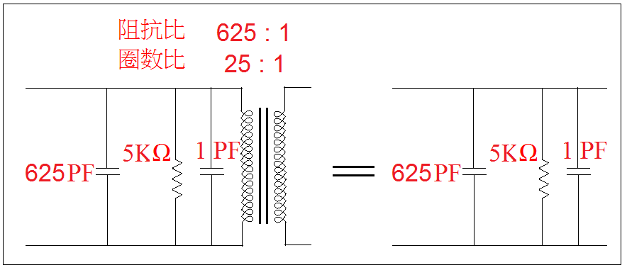
Coupled with the potential of the primary winding, the transformer itself does not consume energy, which is equal to non-existent. see picture:
Connected to a source with 50Ω internal resistance, because of the low internal resistance, 625PF capacitor will not bypass the high frequency, see the picture:
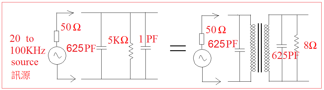
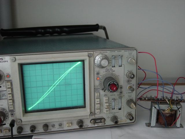
Connect the oscilloscope to the 8Ω resistor to measure the maximum operating frequency of the core. This test does not consider the static current flow factor, but if the working range of the transformer is in the linear region of the hysteresis characteristic curve, even if there is static current flow, the results are a bit different but not too far apart, so there is still reference value, this method is mainly convenient and fast, and ultimately still have to be tested on the machine in the final step.
.
.
IN order To understand the hysteresis characteristic curve, we have to go through an experiment:
Figure 1, the coil is not connected to the power supply, the core has no magnetic force, the compass does not move:
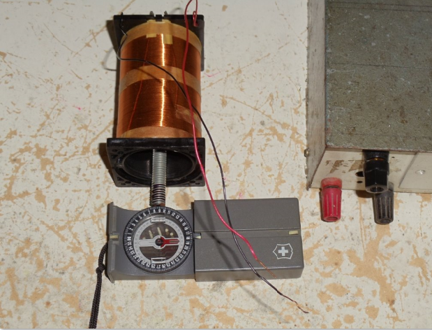
Figure 2, the coil is connected to the power supply, the core has magnetic force, the compass deflects:

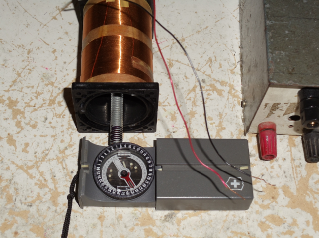
Figure 3 , the reverse power supply connected to the coil, the core has magnetic force, the compass reverse deflection:
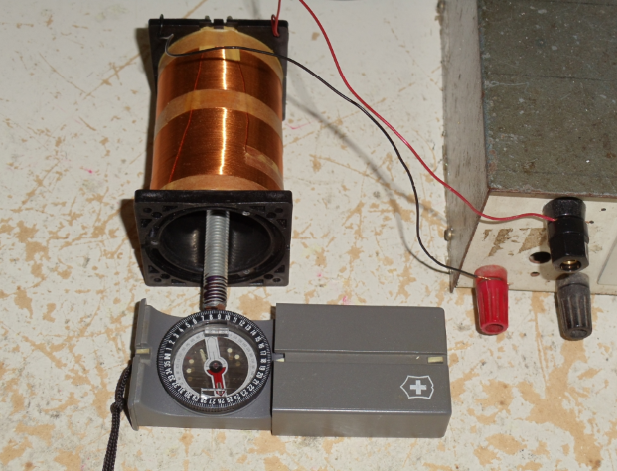
Figure 4 shows the coil is disconnected from the power supply, the core has residual magnetism, and the compass remains deflected:
The problem of the hysteresis characteristic curve is actually the residual magnetic field in the iron core. The stronger the residual magnetic field is, the worse the sound is. See the picture:
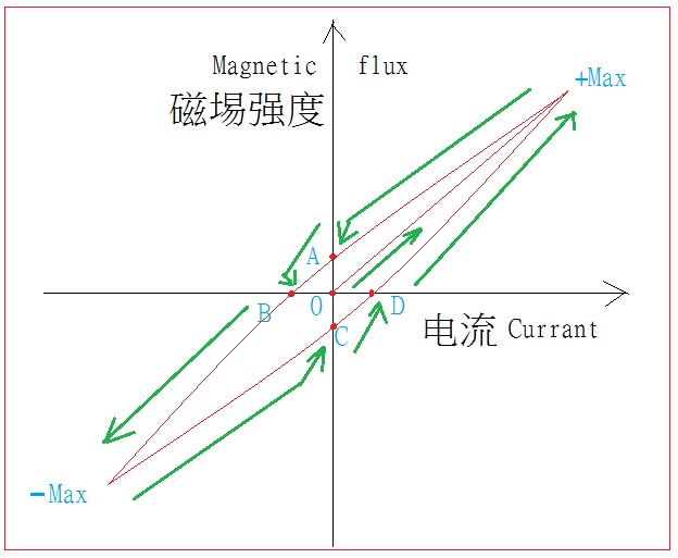
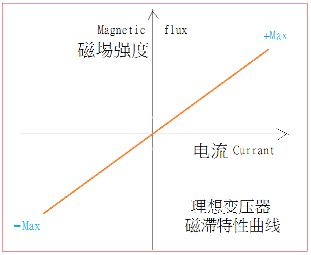
The electric current increases from the O point to the +Max point. The magnetic field strength also increases to the +Max point. Then the current is decreasing and so as the magnetic field strength, then the current at point A has dropped to zero but there is still magnetic strength (remanence). Until the reverse current increases to point B, the remanence is cancelled, and the reverse current increases to -MAX so as the magnetic strength also to the -Max point. Then the current is reducing to 0, but there is still magnetic strength (remanence) until the forward current increases to point D to cancel the remanence magnet field, and then forward current increases. The magnetic strength also increases to +Max, which completes a cycle. If there is no remanence, the magnetic hysteresis characteristic curve will be a straight line, which is the ideal transformer. See the picture:
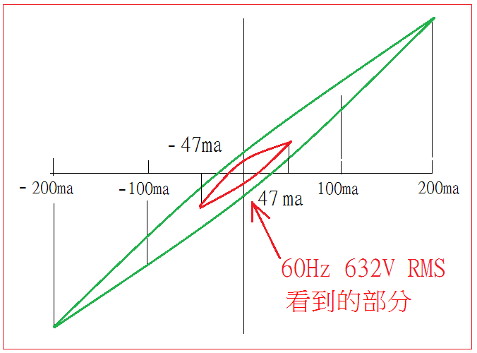
To further understand the specifications of the output transformer, it is necessary to look at the hysteresis characteristic curve of the core. It requires a low-frequency AC power supply of 10Hz 450V 200ma. For example, the primary inductance of the output transformer is 50H, the impedance is 10KΩ, the maximum PLATE current is 100ma, and the maximum output power is 40W:
The primary winding can withstand a maximum AC voltage equal to 10Kx40W square ROOT or 632V RMS
2×3.1416x60x50=18.85KΩ (primary winding AT 60Hz city electrical impedance)
632/18.85=33.5ma RMS ie primary winding peak current 33.5X1.414 = +/- 47.4ma
The maximum current is only +/- 47.4ma by using the maximum AC voltage of 632V RMS from 60Hz mains, but the maximum PLATE current will be 200mA for the static plate current at 100ma. If the power supply frequency reduced to 14.2Hz, the maximum peak current is just +/-200ma at 632V RMS, then we can see the core hysteresis characteristic curve of the actual working range. If the frequency drops to 10Hz Then 450V RMS will do. Look at the picture:
Air gap calculation:
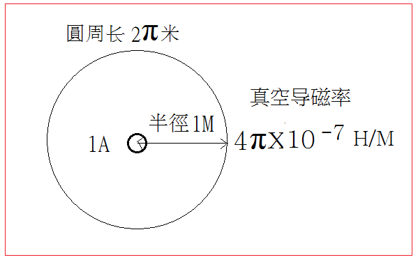
A straight wire passes through 1A of direct current in a vacuum, the strength of the magnetic field on a circumference with a radius of one meter centered on the wire is:
2x〖10〗^(-7)Tesla
The circumference of a circle with a radius of one meter is 2π, and the two numbers are multiplied:
2πx2x〖10〗^(-7)
= 4πx〖10〗^(-7) H/M
This constant is the vacuum permeability, see picture:
The air permeability is the same as the vacuum permeability. The magnetic permeability of the transformer core is several thousand times that of the air. The specific number depends on the core material. The magnetic permeability of the core material can be measured and the air permeability is a constant, knowing the two magnetic permeability, core size and max static plate current can accurately calculate the size of the air gap.
By the time, 100KHz signal generator, oscilloscope, 10Hz 450V low-frequency power supply, as well as AC wattmeter for measuring iron loss, distortion meter and precision LCR bridge, etc., general amateur DIY enthusiasts may not be ready, in order to popularize DIY here, a request is made. If a digital multimeter and an adjustable power transformer are used, a physical core material is given, and no data is available. Can we calculate the primary and secondary turns and the air gap to some extent in accuracy for a designated tube such as 2A3? The answer is yes.
.
.
Before using a digital multimeter and an adjustable power transformer to calculate the number of primary and secondary turns and the size of the air gap, there are three things to know:
1. The effective slope, this is the ratio of the core magnetic strength to the winding current, see picture:
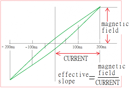
The effective slope of different core materials is different, which is the basis for calculating the inductance of the primary winding of the transformer. Trying to use a general formula to cover different core materials, the calculated result depends on luck.
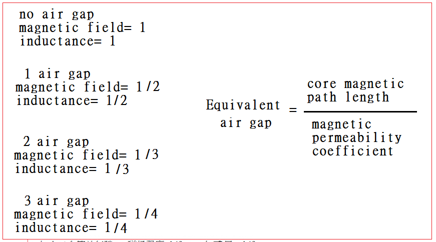
2. The magnetic permeability coefficient is a multiple of the magnetic permeability of the core material compared with the air permeability. For example, if the permeability of a core material is one thousand times that of air, the magnetic permeability coefficient is equal to 1000.
3. Equivalent air gap, under the condition of winding current unchanged, one equivalent air gap can reduce the magnetic field strength of the core material to half of the original (that is, the inductance decreases to half of the original).
Equivalent air gap = core magnetic path length / magnetic permeability coefficient, please see the following table:
.
.
Let us illustrate with an example:
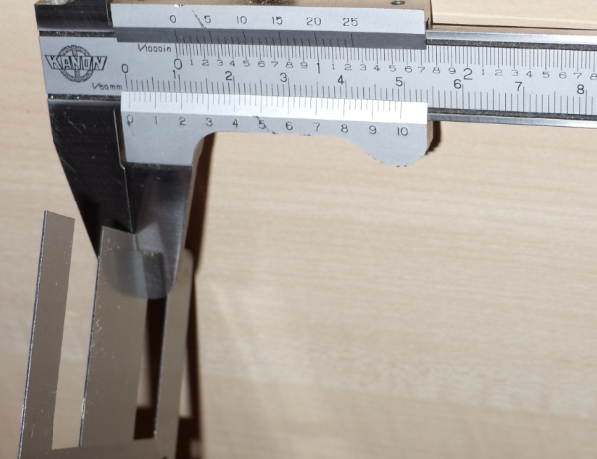
Find a transformer, first take the shell apart, take out the first piece of steel, and then take the coil holder out, see picture:
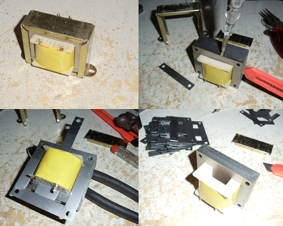
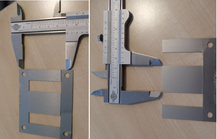
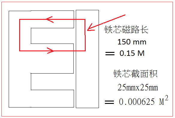
Measure the length of the side and the width of the tongue to calculate the magnetic length of the core and the cross-sectional area of the core:
Remove the original winding, re-wrap 1200 turns with 0.3mm magnet wire, and replace the iron core, no air gap required, see picture:

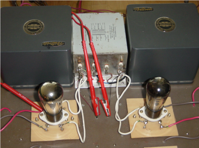
Then find a digital multimeter and an adjustable power transformer:
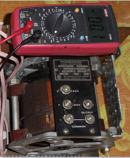
Connect the winding in series with a 100Ω ohm resistor to the adjustable power transformer output terminal, please see picture:
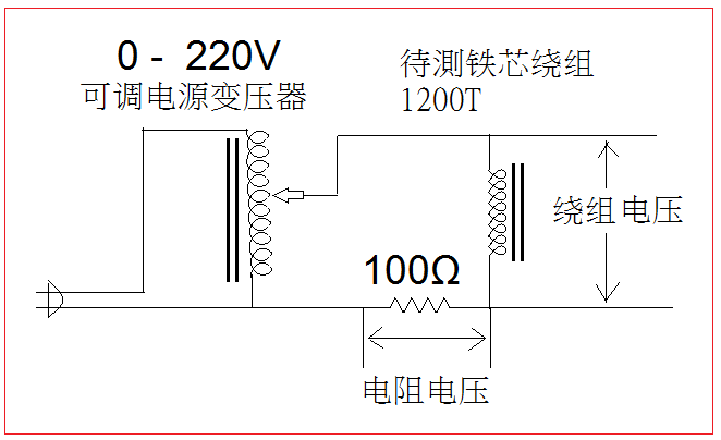
The function of the 100Ω ohm resistor is to calculate the winding current using Ohm’s law, because the voltage is measured with one digital multimeter. The result is shown in the figure below:
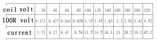
Draw a voltage and current curve:

The figure shows that when the winding voltage exceeds 200V, the current increases rapidly, that is, it starts to move away from the ideal line into the nonlinear region. This shows that the core material starts to magnetically saturate. To maintain the linear response, the winding current should not exceed 34.2MA (RMS). That is, the winding voltage should not exceed 200V (RMS), which reflects the effective slope of the core material.
The magnetic permeability coefficient formula is as follows:
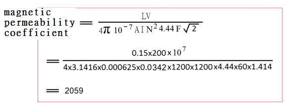
L is the core magnetic path length (m) = 0.15
V is the winding voltage = 200V RMS
A is the core cross-sectional area (m2) = 0.000625
I is the winding current = 0.0342 A
N is the number of winding turns = 1200
F is the mains frequency = 60
Calculate the magnetic permeability coefficient = 2059
This magnetic permeability coefficient formula is not available in any book. It is derived from the principle of Electromagnetism and confirmed by experiments. It is now disclosed. If the winding worker does not understand the formula ,the equivalent air gap can only be relied on estimate, not perfect.
Calculate the equivalent air gap:
= core magnetic path length / permeability coefficient
=150/2059= 0.073 mm
winding impedance = 200V(RMS) / 34.2MA(RMS) = 5848 ohm
winding inductance = 5848 / (2 × 3.1416 × 60) = 15.51 H Henry
winding peak current = 34.2MA (RMS) x 1.4142 = 48.36 MA
Maximum static plate current = winding peak current / 2 = 24.18 MA (peak current is twice the static)
Number of winding turns = 1200
Equivalent air gap = 0.073 mm
.
.
According to the winding inductance (15.51 H Henry), the maximum static plate current (24.18 MA), the number of winding turns (1200) and the equivalent air gap (0.073mm), we can calculate the required number of turns.
Suppose we need a maximum static plate current of 40 MA, the primary winding inductance is 25H. The impedance ratio is 5K: 8 OHM
40MA/24.18MA=1.654 times
1200 turns/1.654=725.5 turns (basic turns)
Basic turns inductance = 15.51H / (1.654 × 1.654) = 5.67H
25H/5.67H=4.41 times
725.5 turns x4.41=3199 turns (primary winding)
3199 turns / 25 = 128 turns (secondary winding)
Air gap = 0.073mmx (4.41-1) = 0.249 mm
The inductance of the primary turns becomes 5.67Hx (4.41 × 4.41) = 110.27H
The air gap is 0.249 mm and the inductance is reduced to 110.27H/4.41= 25H
Calculate is completed:
3199 turns (primary winding)
128 turns (secondary winding)
Air gap 0.249 mm
Suppose again that we need a maximum static plate current of 50 MA, the primary winding inductance is 25H. The impedance ratio is 2.5K: 8 OHM
50MA/24.18MA=2.067 times
1200 turns / 2.067 = 580.5 turns (basic turns)
Basic turn inductance = 15.51H / (2.067 × 2.067) = 3.63H
25H/3.63H=6.89 times
580.5 turns x6.89=4000 turns (primary winding)
4000 turns / 17.68 = 226 turns (secondary winding)
Air gap = 0.073mmx (6.89-1) = 0.43 mm
The inductance of the primary turns becomes 3.63Hx (6.89 × 6.89) = 172.32H
The air gap is 0.43 mm and the inductance is reduced to 172.32H/6.89= 25H
Design is completed:
4000 turns (primary winding)
226 turns (secondary winding)
Air gap = 0.43 mm
From these two examples, we can see that for a same core material, even if the inductance requirements are the same, the larger the maximum static plate current the more the number of primary turns, the thicker the copper wire, indicating the larger the static plate current the bigger the transformer will be, the single-ended output transformer is big and heavy with more expensive for high static plate current. The designer can’t increase the static screen flow arbitrarily because the maximum size of the winding is limited by the core material window.
This example uses the following design:
Maximum static screen flow 40 MA
Primary winding inductance 25H
Impedance ratio 5K: 8 OHM
3200 laps (primary winding)
128 turns (secondary winding)
Air gap 0.249 mm
The primary winding is wound with 3,200 turns of 0.2mm magnet wire, and the secondary winding is wound with three 0.5mm wires in parallel and wound into three layers. The two primary windings are sandwiched by a layer of secondary winding.
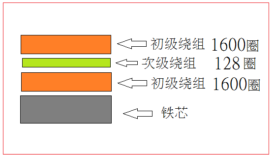
As for many websites have detailed winding making information, so it is over ride here. As for the actual air gap, 0.249/2=0.124mm, because the magnetic lines will pass through the air gap twice, so the thickness is half of the calculated value.

The following is the completion and audition situation, DIY RCA 245 tube amplifier push Tannoy SGM12X speaker
In fact, this is the core of a 0.5mm thick power transformer. If the design is accurate, the overall effect is not too bad. The high-pitched segment is affected by the eddy current loss and the air feels just a bit weak.
The frequency response of a single-ended output transformer is determined by the core material and stray capacitance of the winding and the leakage inductance. The distortion of the output transformer is determined by the hysteresis characteristic curve. The hysteresis characteristic distortion is mainly reflected in two factors:
1. Residual magnetic distortion coefficient is equal to neutralization current over max current, please see the picture:
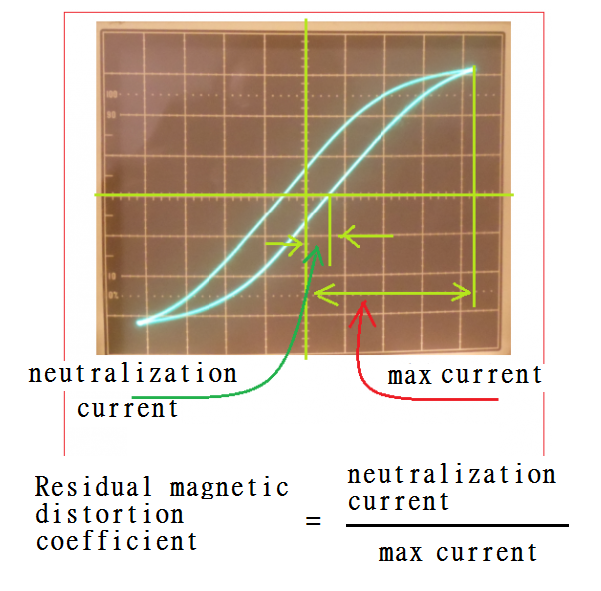
The stronger the residual magnetization, the larger the neutralization current which cancels the remanence, leading to larger residual magnetic distortion coefficient.
2. Peak distortion, please see the picture:
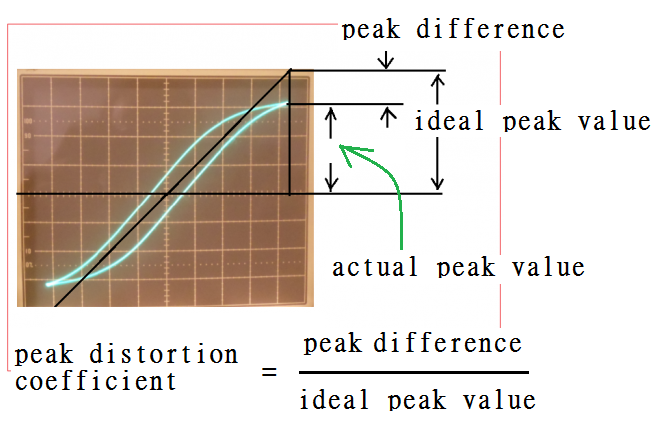
The closer to the magnetic saturation, the larger the peak deviation is, the larger the peak distortion coefficient is.
.
.
Residual distortion and peak distortion are firstly reflected in the excitation current of the primary winding, which in turn affects the output signal. The excitation current distortion of the primary winding is easily seen on the oscilloscope. The effect on the output signal is not easy to see on the oscilloscope, but the ear can tell.
However, the residual magnetic distortion and peak distortion are particularly obvious in the low frequency range. The superior winding technology can only reduce the potential capacitance and leakage inductance to improve the high frequency response, and it is helpless to improve the two kinds of distortion. But there is still some way to do something.
The above-mentioned transformer winding design method shows that a core material can be wound into different specifications, which is in line with the calculation principle. The three parameters, the number of winding turns, the primary inductance and the air gap thickness are mutually constrained. They work together to create different specifications. Among the many different specifications, there is always one that is particularly suitable for the core material, called the optimal scale.
The optimal scale of different core materials is different. The formal transformer factory had set up laboratory tests to obtain the best scale data, in addition to the optimal scale , the copper loss ratio design theory with the optimal scale to achieve the best results, In order to solve the problem of different hysteresis characteristic curves, the famous factories in the last century have been mass-produced for decades, and they have already been thoroughly penetrated, and the source of high-quality iron core materials is superior. DIY is not easy, residual magnetic distortion and peak distortion are reflected in low frequency replay, and low frequency replay is an important factor of sound touching, so the hysteresis characteristic curve of the output transformer core is important. If DIY wants to make high quality single-ended output transformer, don’t stay on those so called public experience formula.
to sum up:
The success of a high-quality single-ended output transformer consists of three aspects: high-quality core material, second, true engineering level winding and air gap design, and high-level hand winding technology. It makes sense to sell the transformer so expensive.
Since the high-quality single-ended output transformer is so expensive, what can it give us?
The answer is that if you match the direct heating triode correctly, you will get an acoustic touching.
.
(End of the article)
.
Appendix 1
.
Tube output transformer hysteresis loop basic concepts:
Most output transformer manufacturers emphasize their multi-layer winding technique and claimed that is the trade secret of good sound quality. The actual case is that IRON CORE plays the most important role. I estimate the iron core gives 70% sound quality while the winding only gives 30%, how come?
A tube output transformer actually is two independent coils winding on ONE iron core. The primary connected to a tube and the secondary connected to the speaker(ohm matching). The primary coil passes energy to the iron core as magnetic flux form (step 1), and the core passes energy to secondary coil back to electrical energy (step 2).
The problem is that some iron core does not response linear. That means the magnetic flux in the core is not pure sinusoidal even the primary source is sinusoidal and leads to distortion on the secondary side. Furthermore, the iron core will convert a certain percentage of magnetic energy to heat, this is also known as hysteresis iron loss. Significant hysteresis iron loss will obviously reduce high-frequency response. An appropriate set up with an oscilloscope can see the iron core hysteresis loop, the SMALLER the loop area the BETTER the iron quality as well as SOUND quality.
.
.
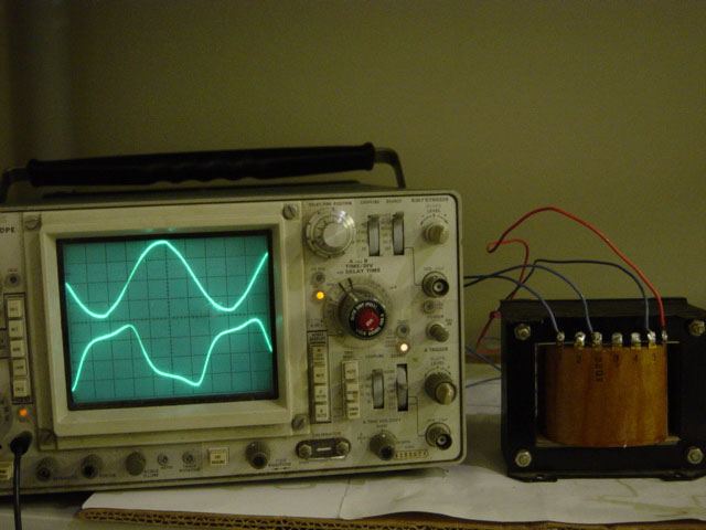
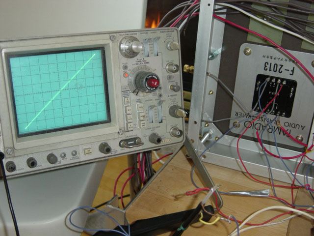
The actual example from a power transformer, the hysteresis loop(see picture below).
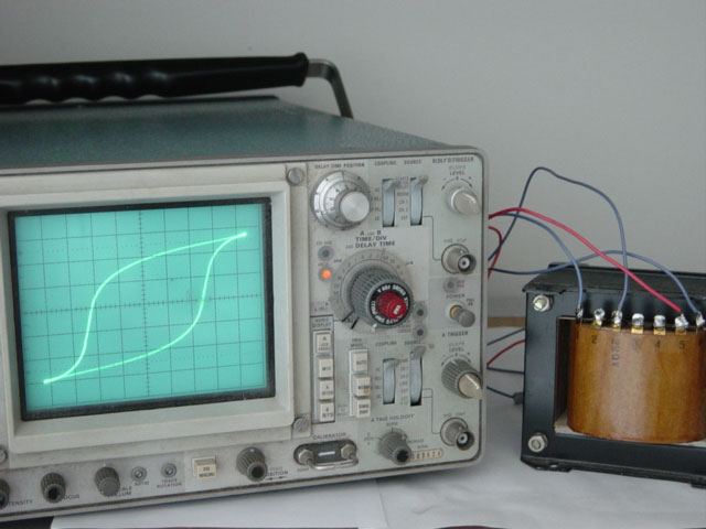
The magnetizing current waveform distortion (lower curve).
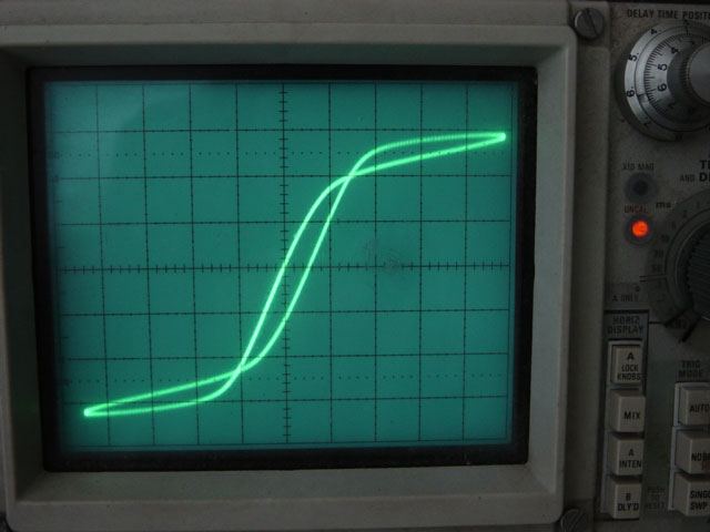
The hysteresis loop from a North American tube radio output transformer.
.
.
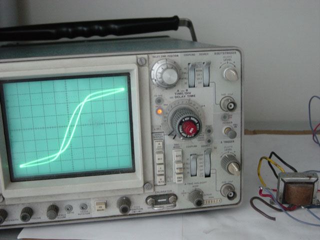
The hysteresis loop from an European tube radio output transformer.
.
.
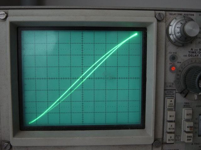
Hysteresis loop from a Tamura F 2013 output transformer, the loop almost is a straight line with minimum loop area to prove excellent sound quality.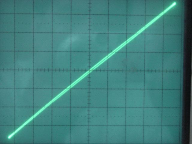
Thank you for visiting!