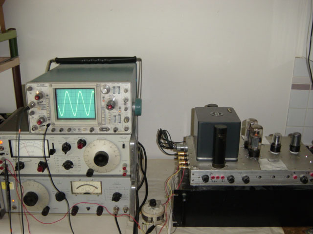
From mid 80’s I went back to tube amplifiers and tried to build a 30W 6L6 push-pull mono block pair with 6SN7 drive tube.
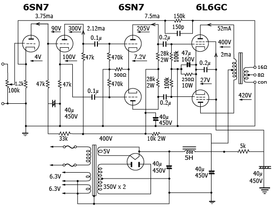
I selected a popular circuit diagram see picture:
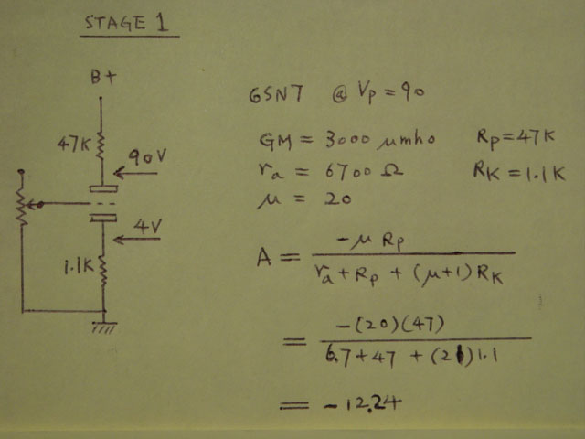
Stage 1 voltage amplifier calculation, plate output. Grid input load of next stage neglectable.
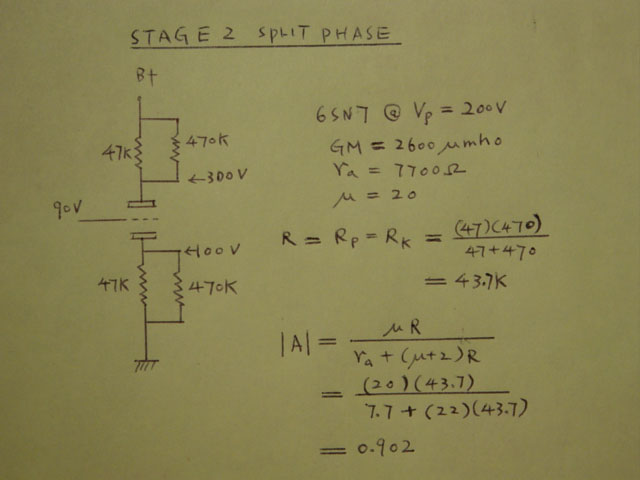
Stage 2 phase spliter calculation, plate and cathode output. Grid input resistor load of next stage parallel to plate and cathode resistor.
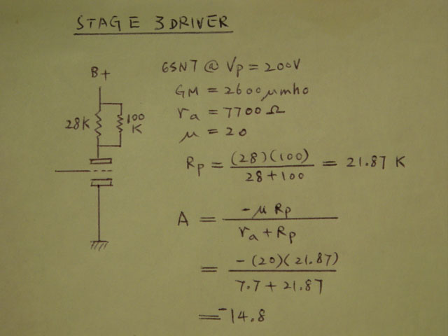
Stage 3 driver stage calculation, plate output. Grid input resistor load of next stage parallel to plate resistor. Cathode resistor neglected due to differential amplifier operation.
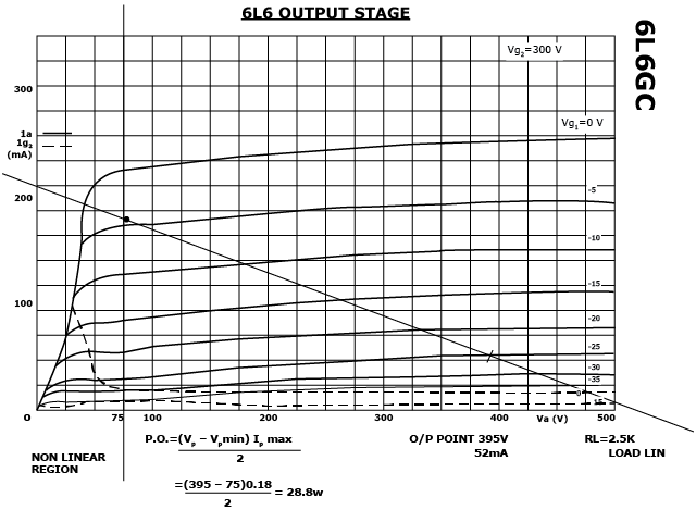
6L6 output stage, pentode connection operating point Vp=395V, Ip=52ma, RL=2.5K
Po=(Vp-Vpmin)Ipmax/2
=(395-75)0.18/2
=28.8W
Grid input 42V p-p for 28.8 Watt push pull output power.
The open loop voltage gain to the power tube is: (NFB not yet considered)
(-12.24)x0.902x(-14.8)=163.4
i.e. 42/163.4=0.257 Vpp
That means 0.257 Vpp input can deive out 28.8W output 6 db NFB arranged, 0.514 Vpp can drive same output.
See 2.5K load line below.
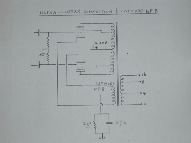
Ok, each stage was working good in linear portion, no overload drive, every thing seemed perfect. The sound quality is quite good but I expected it should be better. After about a month listening I rearrange the output stage as ultra-linear connection and cathode NFB arrangement. ( another -6 db NFB, 1.028V pp input for full output)
Final test result:
Sensitivity: 1.028 Vpp for 28W output
Frequency response:
10 HZ -1.6 db
15 HZ -0.6 db
20 Hz to 45 KHZ +/- 0 db (flat)
60 KHZ -0.6 db
80 KHZ -3 db
Where 0 db=28W power output.
THD (total harmonic distortion)
20 HZ 28W 1.2%
2 KHZ 28W 1.2%
20 KHZ 28W 1.2%
The final sound quality is now much better and can easily drive different type of speakers.