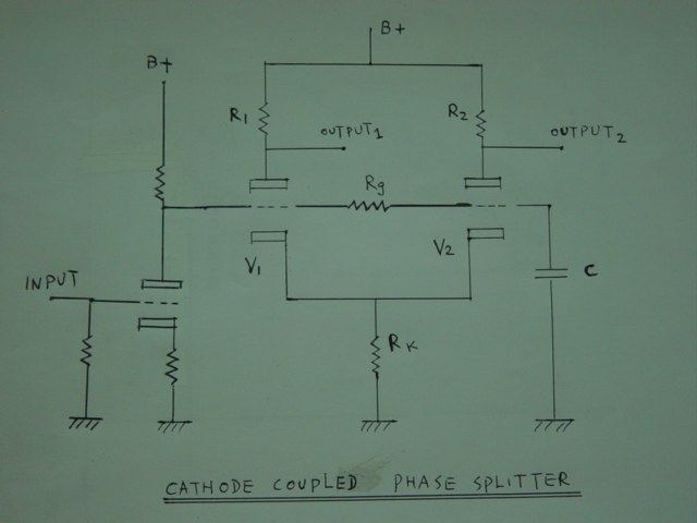
Long tail phase splitter (also known as Cathode Coupled Phase Splitter) is widely used in push pull tube amp driver stage, it is more convenient and simple but the output voltage has about 10% difference between V1 and V2, to use a larger value resistor as V2 plate resistor is a norm in long tail driver for output voltage balance. The practice is adjusting a variable pot while watching a oscilloscope for a best sine wave form.
Please see picture:
Please see the equivalent circuit
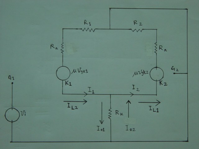
From the equivalent circuit :
![]() <-F1
<-F1
![]() <- F2
<- F2
Then
![]() <- F3
<- F3
![]() <- F4
<- F4
Let ![]() <- F5
<- F5
Let![]() <- F6
<- F6
Then:
![]() <- F7
<- F7
![]() <- F8
<- F8
From F3 and F7
![]() <- F9
<- F9
From F4 and F8
![]() <- F10
<- F10
From the equivalent circuit then:-
![]() <- F11
<- F11
From F9,F10,F11
![]() <- F12
<- F12
![]() <- F13
<- F13
![]() <- F14
<- F14
![]() <- F15
<- F15
![]() <- F16
<- F16
From the equivalent circuit Then :
![]() <- F17
<- F17
From F9, F10, F17
![]() <- F18
<- F18
From F16, F18
![]() <- F19
<- F19
 <- F20
 <- F21
From F20, F21
![]() <- F22
<- F22
From F16, F22
![]() <- F23
<- F23
By current ratio in Rk path and R2+Ra path
![]() <- F24
<- F24
By current ratio in Rk path and R1+Ra path
![]() <- F25
<- F25
Then the out put currents are:
![]() <- F26
<- F26
![]() <- F27
<- F27
From F3, F4, F25 anf F26
![]() <- F28
<- F28
From F22, F23, F28
![]() <- F29
<- F29
![]() <- F30
<- F30
Since triode 1 output voltage = Iout1R1 so that From F30
![]() <- F31
<- F31
![]() <- F32
<- F32
And the voltage gain of triode 1 is equal to output
voltage devided by input voltage Vi so that :
![]() <- F32A
<- F32A
From F3, F4, F24, F27
![]() <- F33
<- F33
From F22, F23, F33
![]() <- F34
<- F34
![]() <- F35
<- F35
Then :
![]() <- F36
<- F36
And the voltage gain of triode 2 is equal to output
voltage devided by input voltage Vi so that :
![]() <- F36A
<- F36A
F32A and F36A are the fomula for gains of tube V1 and tube V2.
By compare F32A and F36A we found that the voltge gain is a bid different between tridoe 1 and triode 2 in case of R1=R2, this is the reason why a variable resistor is connected in series with R2 for adjustment to achieve balance output voltage. Actually by calculation the value of R1 and R2 can be fixed instead of adjusting the additional variable resistor by oscilloscope waveform monitor.
Please note that Rx Ry RAo RBo and (F) are group of resistance
and constants please refer to F1, F2, F5, F6 and F21 respectively.
Please see Marantz 9 phase splitter circuit diagram
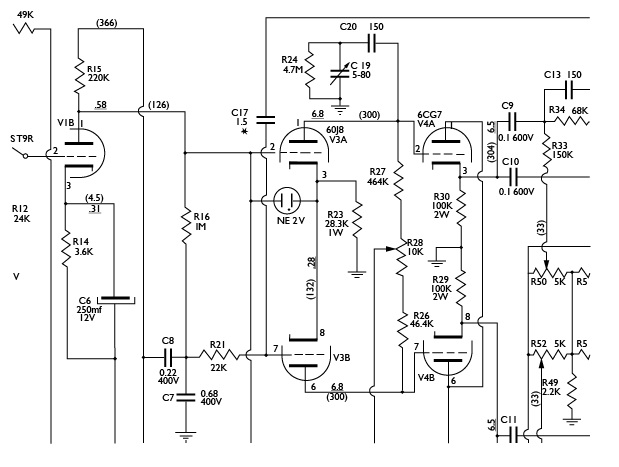
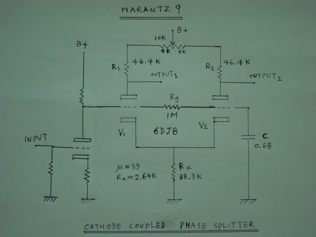
If the adjusting pot is set at 4K and 6K each side so that R1 will
be 46.4+4=50.4K while R2 will be 46.4+6 = 52.4k, we have:
R1 = 50.4K
R2 = 52.4K
Rk = 38.3K
Ra = 2.64K
µ = 33
By F32A V₁ gain = 15.7
By F36A V2 gain = 15.7
This is in balance and the adjusting pot can be replaced with one 4K and one 6K fixed resistor if you desire but I don’t suppose anybody would. This calculation could be a guide line for adjustment, if the balance point is too far away from that point (4K, 6K), the 6DJ8 should be replaced.
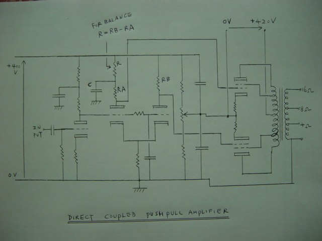
One more usable application for long tail splitter is direct drive stage in Push pull amplifier, as the plate potential to ground of both tube is a bit different and this will ruin the direct drive to power tube. A small modification can get the static balance of both tube plate voltage to suit the power tube drive as the DC out put voltage is also the negative bias of the power tube. The job is simple that a resistor equal to the difference of both plate resistor worked with a filter capacitor can resume the DC balance please see picture:
Thank you for visiting !